This thread has been locked.

If you have a related question, please click the "Ask a related question" button in the top right corner. The newly created question will be automatically linked to this question.

TPS23756: AC source switch to PSE source seamlessly

Part Number: TPS23756

Hi TI,

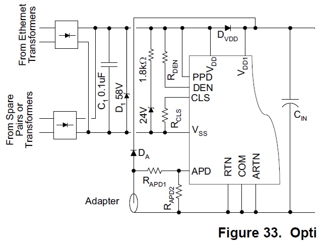
Our customer was try to use the connection below to do AC/PSE seamlessly switch.

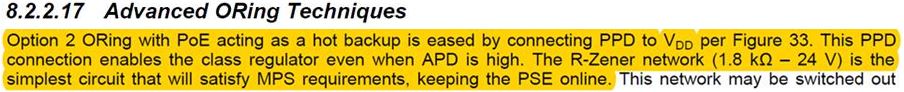
According to datasheet 8.2.2.17, the PSE should keep alive because of PPD enable and R-Zener for MPS requirement.

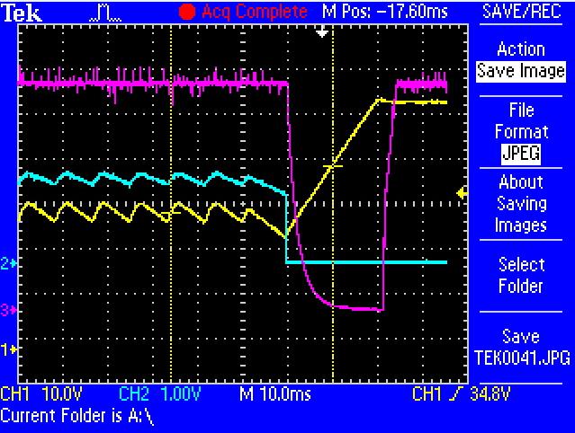
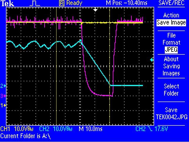
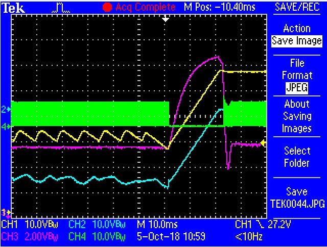
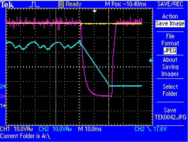
But when AC source removed, we see the PSE must wait for the Hotswap switch fully turn-on then output power.

Here are some question:

1. Why the Hotswap didn't turn-on before AC removed even through PPD pull to high?

2. Is this connection (as Fig.33) could achieve power source seamlessly switch?

(CH2: RTN-VSS)

Thank you very much.

C.T.

  • Hi Chentsu,

    The customer is using the PPD2 function described in section 7.3.11 of the TPS23756 datasheet. In this mode, the class regulator is operating so that the PSE never losses connection (has to re-detect), but still needs to power on to 48V after the adapter is removed, so there is a delay.

    For seamless operation, see the circuit on the right side of figure 33.

    Thanks,
    Thomas Amlee
    PoE PD Apps Engineer
  • Hi Thomas,

    Thanks for your response, here are few more question, could you help to answer by item, thank you.

    1. PPD1: enable hotswap switch and disable classification current, PPD2: enable classification current but disable hotswap switch, am I right?
    2. How the right side of figure 33. achieve seamless operation, could you help to explain it in detail? Thanks a lot.
    3. From datasheet, the right side of figure 33 is design for 48V adapter,
    "An example of an adapter priority application with smooth switchover
    between a 48-V adapter and PoE is shown on the right side of Figure 33." but customer use 24V adapter, is this still work in seamless?

    C.T.
  • Hi Thomas,

    Is there any update for this? Thank you.

    C.T.
  • Hi CT,

    1. That is correct. (section 7.3.11)
    2. DAPD reduces APD hysteresis, so the PSE can provide power before more quickly (the pass FET turns on sooner) before the adapter voltage drops too far.

    With the 30V zener, the 48V adapter would have to drop to 42V for the falling APD hystresis to be met.Using a simple divider, the adapter would have to drop to 35V to meeting the falling APD threshold.

    3. I'm getting more confirmation on this point.

    Thanks,

    Tom Amlee

    PoE PD Apps Engineer

  • 3. This can be done with a 24V adapter. The zener diode & resistor divider would need to be sized carefully to make sure the adapter voltage does not have to fall too far for the APD falling threshold to be met. Let me know if you need assistance with calculating this based on the customer's adapter voltage tolerances.

    Regards,
    Tom Amlee
    PoE PD Apps Engineer
  • Hi Tom,

    Our customer used the right side of Figure33. circuit, but it still doesn't work. Everytime the hotswap switch turns on, the converter portion stop and output voltage goes low.

    CH1(yellow): VDD1 CH2(blue): APD CH3(purple): output 5V

    CH1(yellow): PoE-VSS CH2(blue): RTN-VSS CH3(purple): output 5V

    CH1(yelow):VDD1-RTN  CH2(blue): VSS-RTN CH3(purple): Vc-RTN CH4(green): GAT1-RTN

    From picture3., can see PWM stop during how-swap switch turning on, is this mean converter will disable as long as the hot-swap switch turning on?

    Please help on this case, thank you.

    C.T.

  • CH1(yellow): Vdd1-RTN CH2(blue): Vss-RTN CH3(purple): Vc-RTN CH4(green):GAT1-RTN

    Figure shows during the RTN-Vss voltage goes to nearly zero, TPS23756 DC-DC converter is disabled.Although Vc is still high(CH3), GAT1 stops working.

    Is it implies that as long as we re-start the internal hotswap mosfet , TPS23756 DC-DC converter will stop untill RTN-Vss goes to nearly zero?

    If the phenomenon is true , is there any way to acheive seamless switchover between PSE/AC?  Thanks

  • Hi Chentsu,

    Could you send me the schematic privately? I will send a friend request. I will look into this in more detail.

    Thanks,
    Tom Amlee
    PoE PD Apps Engineer
  • Hi Tom,

    Schematic had sent you in private, please let us know if any, thank you very much.

    C.T.
  • Hi CT,

    Could you send the page of the schematic that contains the circuit for the adapter input? I need to see the implemenation of the Zener & resistor divider ratio on the APD pin.

    Thanks,
    Tom Amlee

  • Hi Tom,
    Schematic had sent you in private, please let us know if any, thank you very much.

    C.T.
  • Hi CT,

    I see that you have sent me the input schematic with the voltage supervisor. Let me know how that works.

    Thanks,
    Tom Amlee
    PoE PD Apps Engineer
  • Hi CT,

    If the customer has resolved their issue, could you mark this thread as resolved?

    Thanks,
    Tom Amlee
    PoE PD Apps Engineer

  • Hi Tom,

    Now our customer doesn't resolve this issue, BTW , they use voltage monitor intend to makes APD voltage drop faster while adapter remove.
    But the issue is the same, when adapter remove, the hotswap switch turns on, and PWM controller stop during this time, so the output voltage drop.

    Best Regards,
    C.T.
  • Hi CT,

    Since they are going from a low voltage to a high voltage, the delay you are seeing is the PD entering inrush to fill the bulk cap to the 48V level. This is unavoidable with the customer's design.

    Unfortunately, we do not currently have a reference design that address Wide Vin hitless transition. In your customer's case, their next best solution would be to do option 3 ORing (slva306a) or using a 48V adapter with option 2 & PPD pulled to VDD.

    Regards,
    Tom Amlee
    PoE PD Apps Engineer