This thread has been locked.

If you have a related question, please click the "Ask a related question" button in the top right corner. The newly created question will be automatically linked to this question.

UCC28780: UCC28780 light load issue

Part Number: UCC28780

Hi,

I use UCC28780 to design a 5Vout design, and I face the issue at light load.

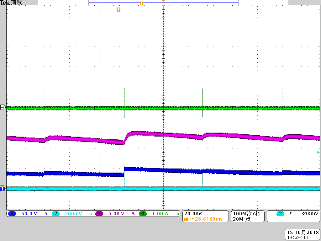
1. When power on the board with 0A load, the output voltage is not regulated to 5Vout, varies between 6.2V~6.9V. It was chared when the burst on period, and discharged when the burst off period. 

The VDD is always higher than VDD(off). The PWML is on with many counts during burst on, and PWMH is disabled.

I power on the board with more than 0.3A, the board works well.

I capture the waveform as below: CH1: Vclamp_cap; CH2:Vcs; CH3: VDD; CH4: Ipri;

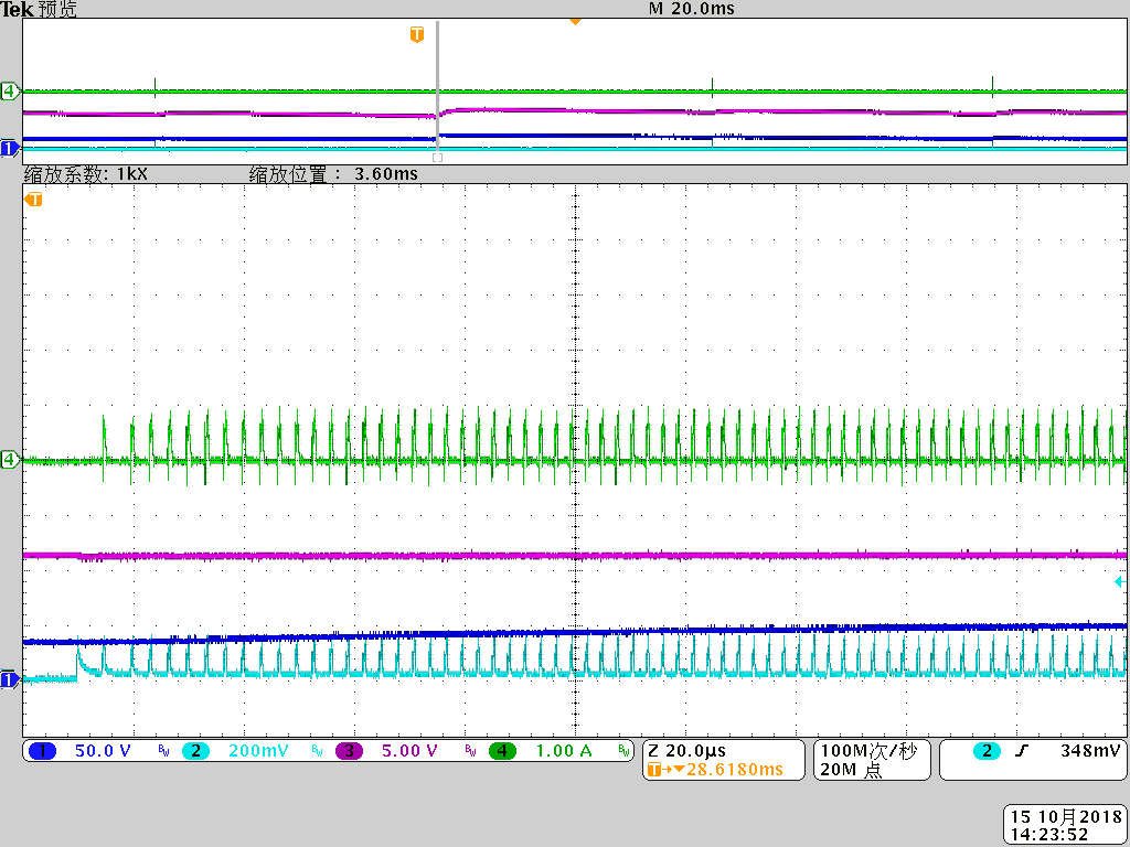
2. When power on the board at 0.1A load with 115Vac. It shows the output voltage is regulated to 5Vout, but the PWML is wrong. The PWML pulse count is not 2. Also the PWMH is good to be disabled.

I capture the waveform as below: CH1: Vclamp_cap; CH2:Vcs; CH3: VDD; CH4: Ipri;

If power on the board with 0.3A load or more, the board can work well.

And then, decrease the load to 0A, the board still works well without any abnormal phenomenon.

It only works failed when power on with 0.2A load or less.

Please help provide your suggestion.

BR

  • Hello

    Thank you for your interest in UCC28780.

    What is the total output power of your application, it will be helpful if you can share your schematic. Do you have any preload resistance?

    Does the same behavior happens when you increase the line voltage @0.2A Load. Please plot PWMH/L on the scope when you see this behavior.

    Regards,

    Sonal

  • Hi Sonal,
    The output power is 5V/3A.
    The schematic is basically the same with EVM board, except the feedback divide resistor (For 5Vout regulated).
    There is no preload resistance.
    The same behavior when power on the board with 0.2A, but 0.3A is OK.
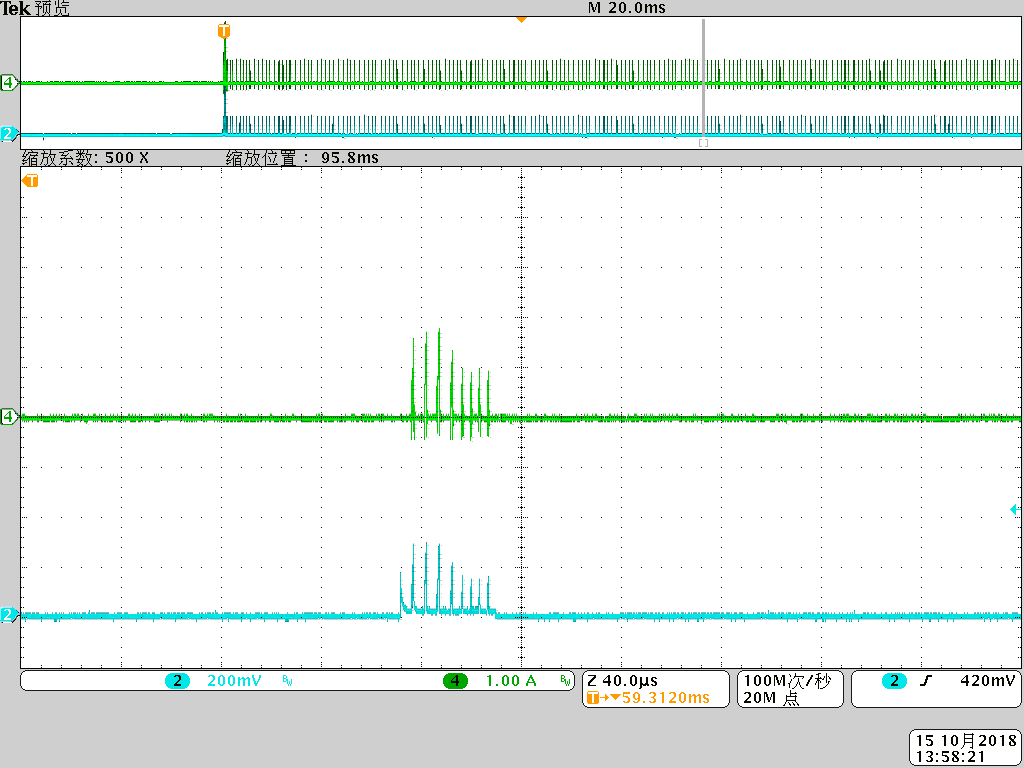
    I don't think that it needs the PWMH/L, and the waveform as above can tell you everything you want to know.
    The PWML is on when there is magnetizing current, and the PWMH is always off because of no negative resonant current.

    BR
  • So, the problem here is since you have only changed the feedback resistor divider for 5Vout/3A, you are delivering very low power than what it should @ full load 20Vout/2.25A, which means the overall efficiency is going to be bad and the Aux winding voltage is going to be much lower than what it should be in your case it seems to provide the Vdd_on voltage to start the controller. I will still recommend to check it once.
    Please have a look at the design calculator attached below you can change the Vout to suit your design and modify all the components starting from the trun ratio of the transformer, this will solve your overvoltage problem @NL condition.
    www.ti.com/.../sluc664