This thread has been locked.

If you have a related question, please click the "Ask a related question" button in the top right corner. The newly created question will be automatically linked to this question.

LM5150-Q1: How to select an appropriate resistor between PVCC and AVCC

Part Number: LM5150-Q1


Hello,

My customer asked some questions on LM5150-Q1 as following.

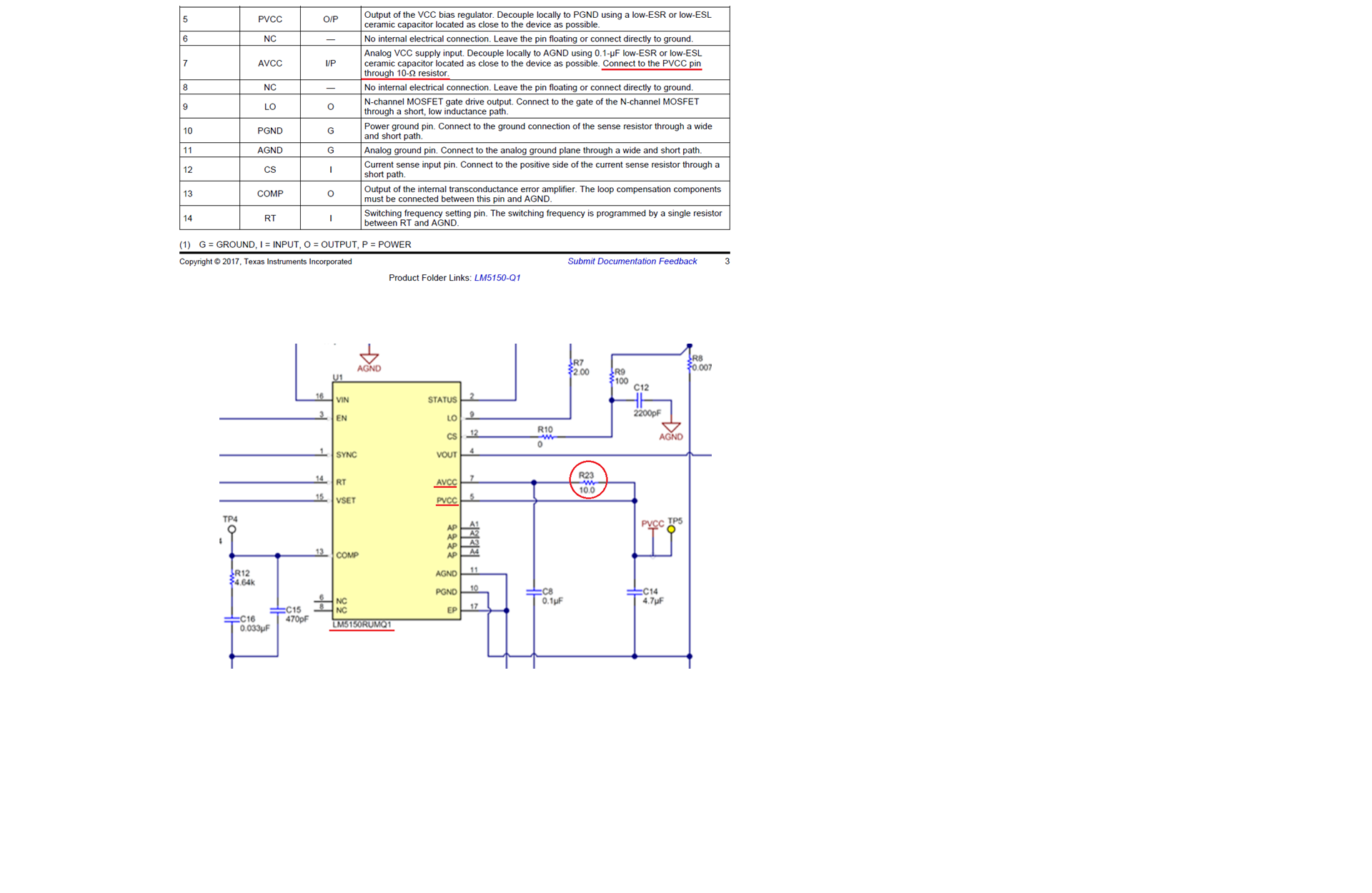
  1. What’s the purpose of the 10 ohm resistor between PVCC and AVCC as schematic below?
  2. How can I calculate or select an appropriate resistance of this resistor?
  3. What’s the possible side-effect when short directly or open a series 10 ohm resistor between PVCC and AVCC?

Best regards,
DY

  • Hi DY,
    This resistor is to help filtering out the switching noises from the PVCC which supplies the driver, so the AVCC is quiet for the analog circuit bias. Switching noise from the driver is usually in the tens MHz range (gate current pulse width is in the range of 100ns). Make the RC to a few hundreds kHz will adequate to filter out the switching noises. Do not use a too large resistor because it also causes dc voltage drop and losses. Recommend 10 Ohm there, and let's set the RC corner frequency to about 100kHz to 200kHz, then you can select the C (C8 in the drawing).

    Hope this clarified.

    Thanks,
    Youhao Xi