This thread has been locked.

If you have a related question, please click the "Ask a related question" button in the top right corner. The newly created question will be automatically linked to this question.

LM3404: The adjustment of output current

Part Number: LM3404

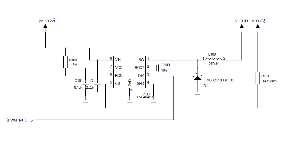
Hi, I'm trying to use LM3404 to build a LED driver module. My input is a 12~13.2V battery, output is to driver 4 LED lamp. On each lamp there are 8 LEDs, each 2 LEDs in parallel become a group, and 4 groups line in serial. The forward voltage of the LED I use is 2.9V, and there are 4 lamps going to connect to the LM3404

The schematic of the driver and each lamp is in the attachment.

The issue I ran into is that when I connect only 1 LED lamp into the system, the current is around 110mA, but when I put a second lamp in to the system, the current stays the same and the brightness drops. After I put all 4 lamps in parallel on the output, the current is still the same.  I tried to change the input PWM frequency from 20K~ 200K, adjusted the resister on CS pin (reduced value), but the output current seems limited. 

Could anyone suggest how to modify to increase the output current? The estimated output is to reach 800mA on 11V output voltage.

Thank you so much!

  • Hello Nan,

    Did you go through the datasheet to design your LED driver?  What is V OUT- connected to?  The connections for the current sense resistor and the load need to look like the attached schematic.  It will not sense current correct as you have it drawn.  I don't see where the Rcs resistor is tied to ground and even if it was the CS pin (pin 5) is connected on the incorrect side of R101.

    Ron value is much too high for 270 uH inductance.  The switching frequency will be low and probably running discontinuous current so it won't regulated correct.

    You cannot have four 2.9V leds in series with voltage tolerance running from 12V.  A buck converter requires the input voltage to be higher than the output voltage.  The output voltage also has 0.2V for the current sense resistor when it is operating correct.

    BR, 

  • Hello Irwin,

    Thank you so much for the reply. I apologize I made a mistake in the schematic while uploading the file, the actual setup of the Rsns is same as the way in the schematic you post.

    I'm thinking about maybe I shouldn't use it to drive 4 leds in series, but the test I did is I removed 1 led in each series, and the total current is still limited to 140mA while I tried to connect more 3-series-led lamps into the system.

    I'll do some test on the Ron and the status of the inductor.

    Thank you again!
  • Hello Nan,

    I have not heard back from you so I believe you may have solved the issue.
    The thread will close now but will reopen if you reply.

    Best Regards,