This thread has been locked.

If you have a related question, please click the "Ask a related question" button in the top right corner. The newly created question will be automatically linked to this question.

LMZ30606: No Output

Part Number: LMZ30606

Hello Team,


We have a problem in using LMZ30606:

We convert 5V to 3.3V by using this chip, and we found that there is no output.

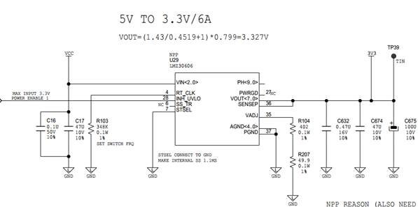
At beginning we thought maybe the INH signal(as red block show) is wrong, and we cut this signal from source, there is still no output. And if we connect it to ground, output appears (although output is incorrect, only 1.35V).


While refer to datasheet, chip should be enabled with INH floating, cause internal pull-up exist.

So I want to confirm it from you, if this chip could be enabled while INH floating?


thanks,

Bell

  • Hi Bell,

    How many customer boards/ units have this issue? The device has an internal pull up current source that will enable the part even if INH is left floating. Also do you have the PCB layout for this? From a schematic point of view, this circuit follows the recommendations in Table 4 for 3.3V application. 

    Regards,

    Jimmy 

  • Hi Jimmy;

    As you know, we implemented two LMZ30606 in our design, and there is output issue in our prototype:

    Circuit 1: 5V -> 3.3V, see attachment 1 for schematic;

    Output: constant 1.3V, Cannot change output’s value by adjusting resistors connected to VADJ.

    Circuit 2: 5V -> 1.5V, see attachment 2 for schematic;

    Output: constant 1.6V; Cannot change output’s value by adjusting resistors connected to VADJ.

    We suppose: Pin ‘PH’ and pin ‘DNC’ are connected currently in layout, will that be cause of output issue?

    Could you help to check the schematic? and could you help for confirming the suppose? Any other suggestion for using this part, pls let us know.

    Recently, we also contributed a demo with LMZ30606 manually (see attachment 3 for schematic), but it also doesn’t work, and the output is 2.5V constantly, no matter we adjust resistors connected to VADJ or not.

    Do you have any ideas for why doesn’t it work?

    Thanks for your support.

    Bell

  • Hi Bell,

    I've attached a simple schematic review I did for the U29 and U32. The schematic follows the recommended component values so I don't think it's anything component related. As I mentioned previously, leaving INH open will still allow the part to switch. I'm curious to take a look at their PCB layout if you have it. Particularly I'd like to see how they route their SENSE+ trace(close to the module or further down at the load). If they have long output traces, it would be preferred to connect SENSE+ pin to Vout at the load to improve load regulation because of I-R voltage drop between the output pin and load. 

    Also since PH is the phase switch node it should not be connected to anything else. The DNC pins are test mode pins that are connected to internal circuitry and can affect the output voltage regulation of the device if accidentally connected to the PH copper island. LMZ30606_SchematicReview.pdf

    Regards,

    Jimmy