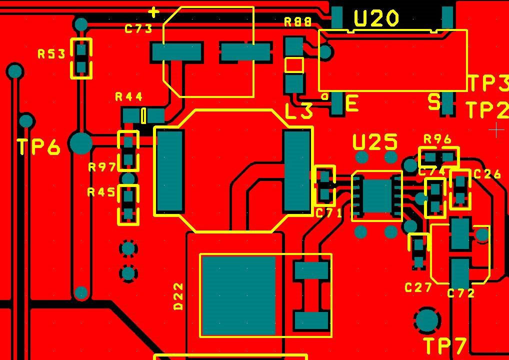
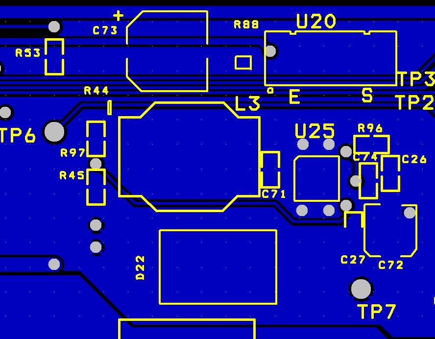
We have been into production for years with a board having LM34910 as one of the regulators. This is the main supply (logic circuits, 5V) of the board. The board has a microcontroller and a series of opto-sensors. The total power consumption (which is almost steady) is about 250mA. As the board was designed by a third party consultant at the time, we do not know the design parameters they used to. In the past a research on a similar board revealed that the values of the main inductor and the output capacitor were not the best solution and we believe this could be the case in this board as well. Nevertheless we have produced these boards in the past (around 15K) without a problem.
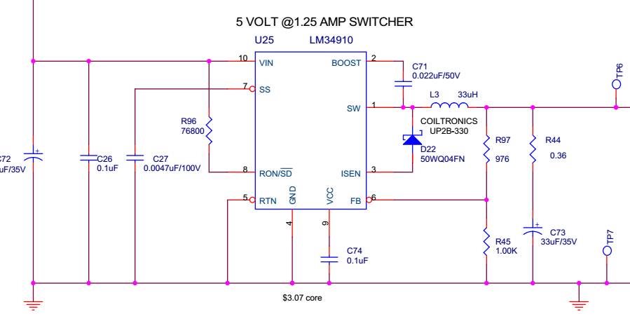
Here is the original circuit:
Recently out assembly manufacturer needed to add alternate components as the original parts specified were hard to find or were obsolete. It seems that after a point some of the boards (10 out off 1000) fail to communicate if we connect all or part of the load (opto-sensors), as a result of instantaneous under-voltage when the microcontroller tries to activate through a FET the LED power.
The parts replaced are D22 and L3.
| Part Designator | Original Component P/N | New Component P/N |
| L3 | Eaton/Bussman, UP2B-330-R | Coilcraft, DO3316T-333MLD |
| D22 | Vishay, VS-50WQ04FNTR-M3 | Diodes Inc, SBRT10U60D1-13 |
Our manufacturer says that the L3 tolerances are such that a higher inductance make the boards fail. As a proof he used a part with less inductance for L3 (27uH) and made these boards work.
However a colleague of mine, used the old D22 part instead (with the new 33uH inductor) and fixed his boards as well.
We have also noticed that heating the boards (after soldering task etc) makes the boards working until they cool down, where they start failing again.
Also if we start removing the loads (opto-sensors) one by one the boards become operational again.
It seems that the circuit is affected by the load (which is how we identified the problem, initially).
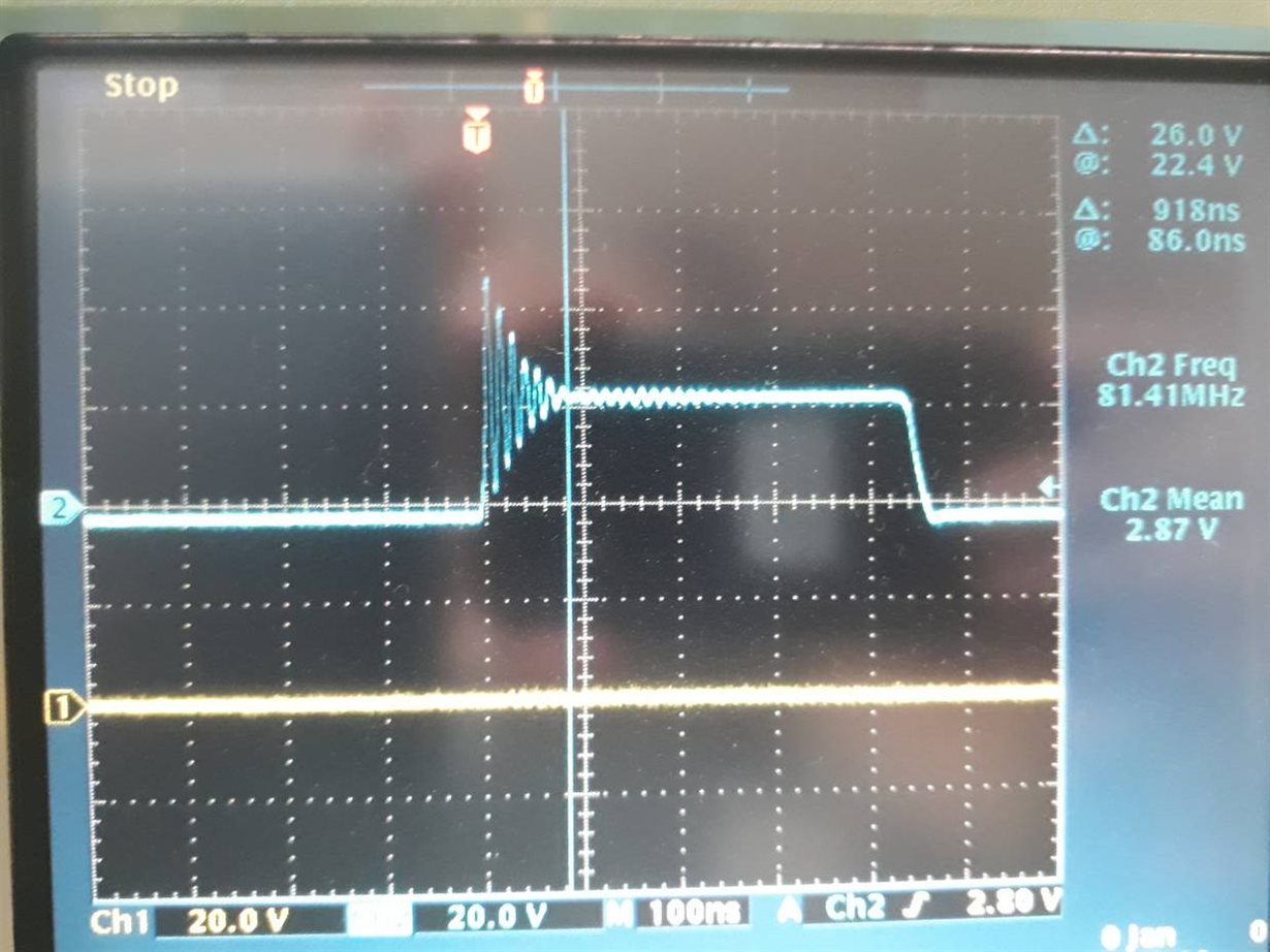
In order to check things myself, I measured the circuit with my scope at Pin 1 of the regulator on a good working board from the past (ie. original components). The regulator seems to work in continuous mode at 454KHz (as set by R96). However the pulse shows some ringing:
Good board, Output of Switcher.
I then instructed my colleague (I do not have direct access, this is in another location) to measure the same point on a failing board:
Bad board - not working, output switcher
It seems that the switcher works in a non-continuous mode (at about 60KHz).
Also note that after the pulse is finished (the small rectangular peak in the scope) the output voltage is 0. Later on a ringing happens and increase this level to 5V that remains till the next pulse.
It seems that the diode plays a critical role in this and the only obvious difference might be the Vf level of the diodes, as checking the plots seem to have 100mV difference.
Can you please explain how the diodes can affect the circuit and which parameters are critical?
As you may understand the boards are already manufactured and the best remedy is to change as few parts as possible. Our manufacturer proposes a slightly lower value inductor, but we have seen that the diode may also fix the issue. What is your recommendation?
Thanks in advance,
Ilias


