This thread has been locked.

If you have a related question, please click the "Ask a related question" button in the top right corner. The newly created question will be automatically linked to this question.

UCC27211: H bridge application where the same driver keeps failing

Part Number: UCC27211

Hello,

I apologize for taking so long to respond. I had to attend to another project.

The problem remains after replacing the 5600 pF bootstrap capacitor with a 0.1U capacitor.

The problem is intermittent. I can replace the chip and it will operate without issue several times.  Somewhere between the 2nd and 10th power-up, my 48V bus drops to 3V as my power supply goes into current limit. IR imaging shows that the UCC27211DR is well over 90C case temperature in less than 3 seconds after power up. The chip is fried as the board cannot be recovered until the chip is replace. This isn't a "one off". I have 10 boards with the exact same problem.

I will replace the chip today and take scope data. In the meantime, do you have any other suggestions?

Thank you.

  • Hello Jerry,
    I would first confirm if the power dissipation in the gate driver is reasonable, or if it is the cause of the temperature rise.
    Refer to the UCC27211 datasheet section 9.2.2.5 which gives details on determining the gate drive power. If the total mosfet gate charge is high, and/or the switching frequency is high the temperature rise may be from gate drive power dissipation.
    Can you please confirm again, the values of the VDD capacitor, gate drive resistor(s), confirm if 0.1uF is the bootstrap capacitor.
    Also the MOSFET part numbers, and the switching frequency you are operating.

    Scope plots will be helpful to help determine what may be the issue.

    Regards,
    Richard Herring
  • Hi Richard,

    Thank you so much for the quick response! Here is what I have now:
    Vdd = 15.8V
    Vdd capacitors: 1 uF // 0.01 uF
    Transistor: IRFL4315TRPBF, Qg < 19 nC @ Id = 1.6A, Vds = 120V, Vg = 10 V
    Bootstrap capacitor confirmed as a 0.1 uF, 100 V, X8R CGA5H2X8R2A104M115AA

    Still working on board repair and getting scope data.

    Again, many thanks

    Jerry Frank
  • Sorry forgot to add that the frequency of operation is 125 kHz
  • While trying to get the board to survive long enough to take data, I think I stumbled upon the issue or issues. 

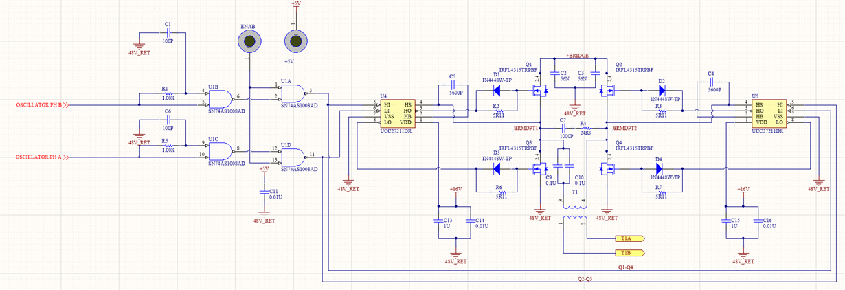
    Originally, I had the "ENAB" port wired high. This means that my gate drive signals would start as soon as the 5V supply came up. The 5V supply comes up in about 8 ms. The 16V supply - Vdd for the UCC27211 -takes well over 50 ms to come up to full voltage. I am not sure how this could kill the gate driver as my load is a 3.3 K resistor and not a transformer, but it seems to be a bad idea. I am now making sure that the 16V supply is up before enabling gate drive. The second issue I found is a poorly chosen part. I am using an RC delay in front of a SN74AS1008AD quad AND gate. During start-up, occasionally there is a tremendous amount of noise at pins 3 and 11 which I think is the gate oscillating due to the slow transition.  The oscillations are in the low MHz which I can see causing problems. But I would expect a shoot-through issue and end up with dead FETs instead of a dead driver. Some random sample of start-ups are below. Please note that in order to get the board to survive long enough to take data, the 48V was disconnected from the bridge.

    My plan is replace the AND gates with Schmitt triggers. I will let you know how it goes.

    Thanks again.

    Jerry

  • Hello Jerry,

    Thank you for the update. Of the two issues or concerns you mentioned, the high frequency oscillation (or switching) on the driver inputs is the likely cause of the failures. This can cause excessive power dissipation in the driver from the gate charge and frequency standpoint, but more importantly the drive train is not well controlled which can result in excessive ringing on the switch node which can result in high stress on the driver.

    Regarding the enable coming up before VDD, which results in the driver input signals being present before UVLO, the driver should not be stressed by this specifically. But there is a concern about the proper timing signals to the power train. If there is a soft start sequence running before the driver can operate, there would be a large number of cycles that is not propagated to the power train if the driver is in UVLO. There is also a UVLo delay to consider, which is typically ~20us on the UCC272xx drivers.

    When you confirm the driver inputs and outputs do not have the high frequency unexpected operation, and the power up sequence is as you expect; please update us on the results.

    Regards

    Richard

  • Hi Richard,

    I have now ensured that the logic signals do not appear before the 16V Vdd is at full voltage. I also changed out the plain AND gates for Schmitt triggers and it works perfectly.

    Thanks so much for your time.

    Jerry Frank

  • Hi Jerry,
    That is very good news indeed. Hard failures are obviously a major concern.
    Thank you for posting the problem resolution details so others on the forum can benefit.
    Can you confirm that the issue is resolved by selecting the green button on the thread, that helps us out a lot.

    Regards,
    Richard Herring