This thread has been locked.

If you have a related question, please click the "Ask a related question" button in the top right corner. The newly created question will be automatically linked to this question.

TPS63710: Current Limit Behavior

Part Number: TPS63710

Hi Team,

Could you please comment if the OCP operation is what we expected and explain the current limit behaviors according to below waveform step by step?  Thanks!

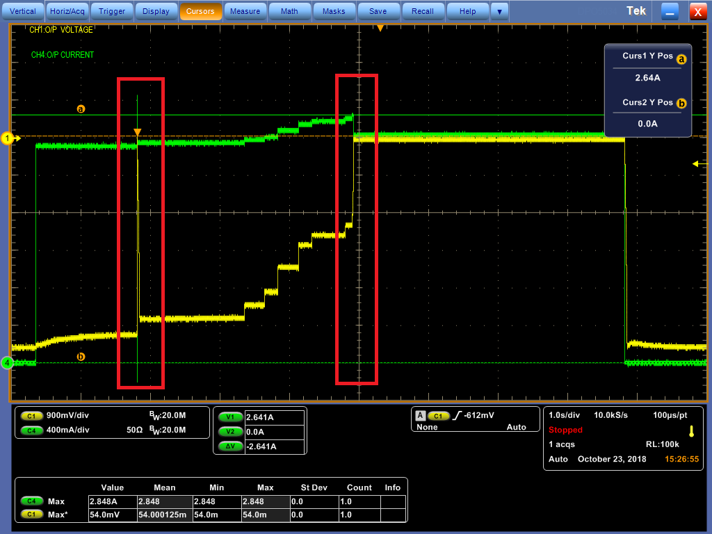
The design is +12V to -5V/1A. The OCP test was done by e-load. The first OCP was triggered while the output current increased to 2.3A, then the device kept switching till the output current up to 2.6A.

Ch1: Output Voltage; Ch4: Output Current


Best regards,

Sam Ting

  • Hi Sam,

    It would be best to add the inductor current to the waveform, as this is what is actually limited by the device.

    As well, electronic loads very often have a not smooth behavior as we see here. You will see different behavior with a resistive load.

    The current limit is explained in section 7.4.3 of the D/S. This is exactly what we see here.

    In the first red box, the eLoad has momentarily drawn much more than the programmed current and basically shorted the output. This is 1 issue with electronic loads. Since Vout drops too low (below -4.5V), the device restarts.

    What we see after this first red box is the device trying to restart. This is a different state than you are in at the beginning.

    As it tries to restart, the load is so high that Vout never reaches the setpoint. So, further increases in load current merely reduce the load resistance and give a lower Vout across the constant output current.

    In the final red box, the eLoad is basically shorting the output and so there is no output voltage anymore.
  • Hi Chris, 

    We'd like to know more about the operation in the first red box. Could you please explain more about the description below? Thanks!

    “the eLoad has momentarily drawn much more than the programmed current and basically shorted the output. This is 1 issue with electronic loads.”

    Best regards,

    Sam Ting

  • Hi Sam,

    Please zoom in on the red box with the scope. You can also retake the same measurement with a resistor load instead to see a difference.

    What I see is that the green trace goes far above a ~2.3A level. Because of this much overcurrent, Vout collapses and the device proceeds with a restart. Adding the CAP pin voltage to the scope should show the restart.
  • Hi Chris,

    Please find the zoom-in capture on first red box. We want to know why the output voltage drops to zero and then recovers.

    As you mentioned, it seems that Vout collapsed because the undervoltage lockout protection was triggered while the output voltage reaches 90% of the target output voltage, then the device shuts down and initiates the restart cycle. is it right?

    Ch1: VOUT; Ch2: SW; Ch4: IOUT

    Best regards,

    Sam Ting

  • Yes, that is correct. If you look at the restart of Vout, the load current will probably be close to 0. Again, this is just due to the operating behavior of the electronic load.

    Is there an actual issue with the device in the application or are you just curious about the behavior?
  • Hi Chris,

    There is no problem now, the customer just wants to ensure that the behavior meets our expectations. Thanks for your support!

    Best regards,
    Sam Ting