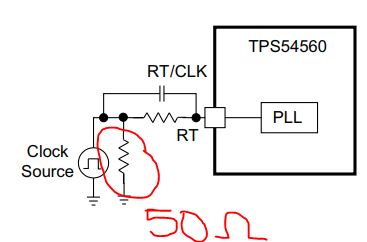
I am using an LTC6900 running at 485kHz as system clock - this is a low impedance (100 ohm) output going from 0V to 3V3.Reading section 7.3.11 of the datasheet and referring to fig 25 (LH part). I am confused whether the series or shunt resistor is supposed to be 50R and what the other resistor should be. I see the parallel cap should be 10pF. Can anyone clarify please?

-
Ask a related question
What is a related question?A related question is a question created from another question. When the related question is created, it will be automatically linked to the original question.