A related question is a question created from another question. When the related question is created, it will be automatically linked to the original question.
If you have a related question, please click the "Ask a related question" button in the top right corner. The newly created question will be automatically linked to this question.
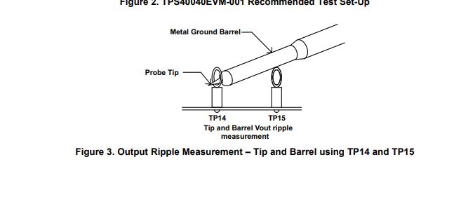
How are you measuring the output votlage? Are you measuring with the tip adn barrel method?
One possibility is that high frequency noise is coupling from the input of the converter to the output of the converter or from the switch node to the output. You can also probe the input and SW node, one at time to check for any noise or ringing.
If it is high frequency ringing, you want to optimize your input capacitor loop. You can also add a high frequency bypass capacitor directly next to the input and/or at the output as well.
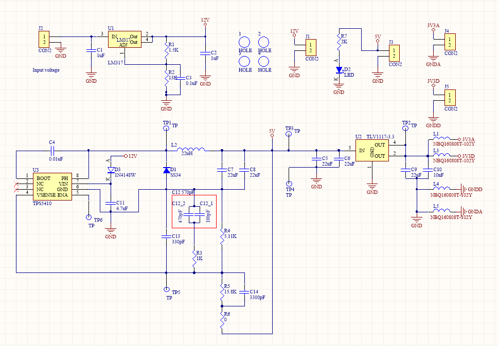
hello,dear Katelyn ,i use tip to measure the waveform, but some question i need to ask , i don't the guide of tps5410 with pole . i don't know what frequent cal on the user guide of tps5410, the frequent mean what? i only know the resistor and cap will effect the frequency, but user guide didn't tell us what frequency mean. so, i don't know how to choice the cap with input cap. such like u say if i change the input cap, i will change the cap C11, and i don't know what value to use. because i design the this circuit i will use for electric tool circuit.so it maybe will connect the mcu. so the cap value will not to high or low it will effective the electric tool. maybe u can give me the suggestion .because i trust u r the expert of power .
and this problem is confuse me many day , could u reply me immediately .
because i need to solved this problem in short time.
my big problem is i need to solved the noise .
and i need to reduce the ripple of voltage to 3~5% because i need to past the emi/emc standard.
so this power circuit is very important.if it could't ,we will give up to use for tps5410.
as u say use another measure could reduce the Output Noise. but i have some problem need to ask. if i change the measure method that mean like i am test the feature of Oscilloscope. not like to solved the high frequency problem.I need to resolved by hardware circuit and as u supply file of document.It also helpful but it look like that meany problem in layout build the high frequency and noise. such like u say, i need to reduce the HF problem. if I could , i think eliminate the oscillator of high frequency is the almost method to solved. so can u give me the more method to solved?
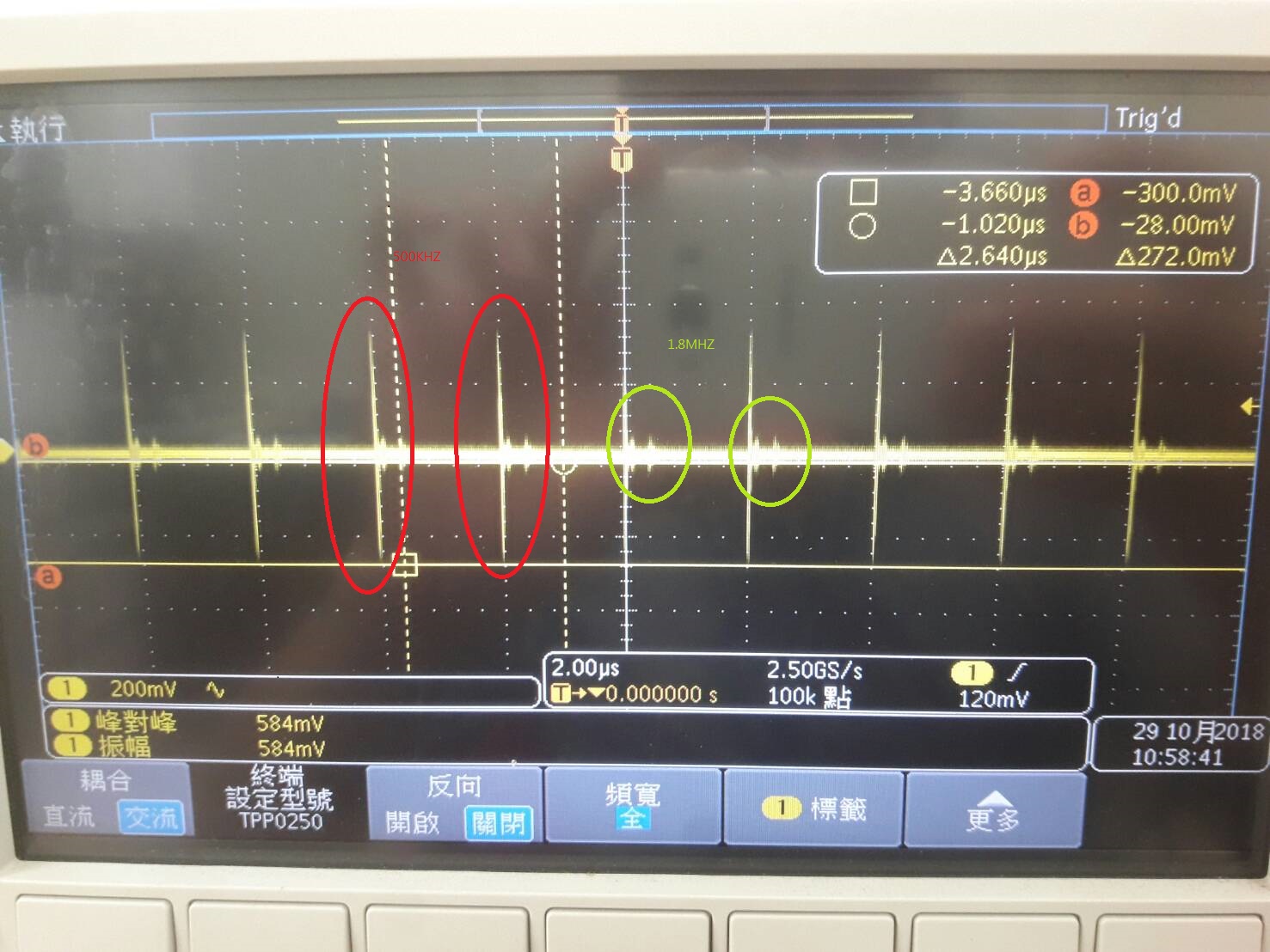
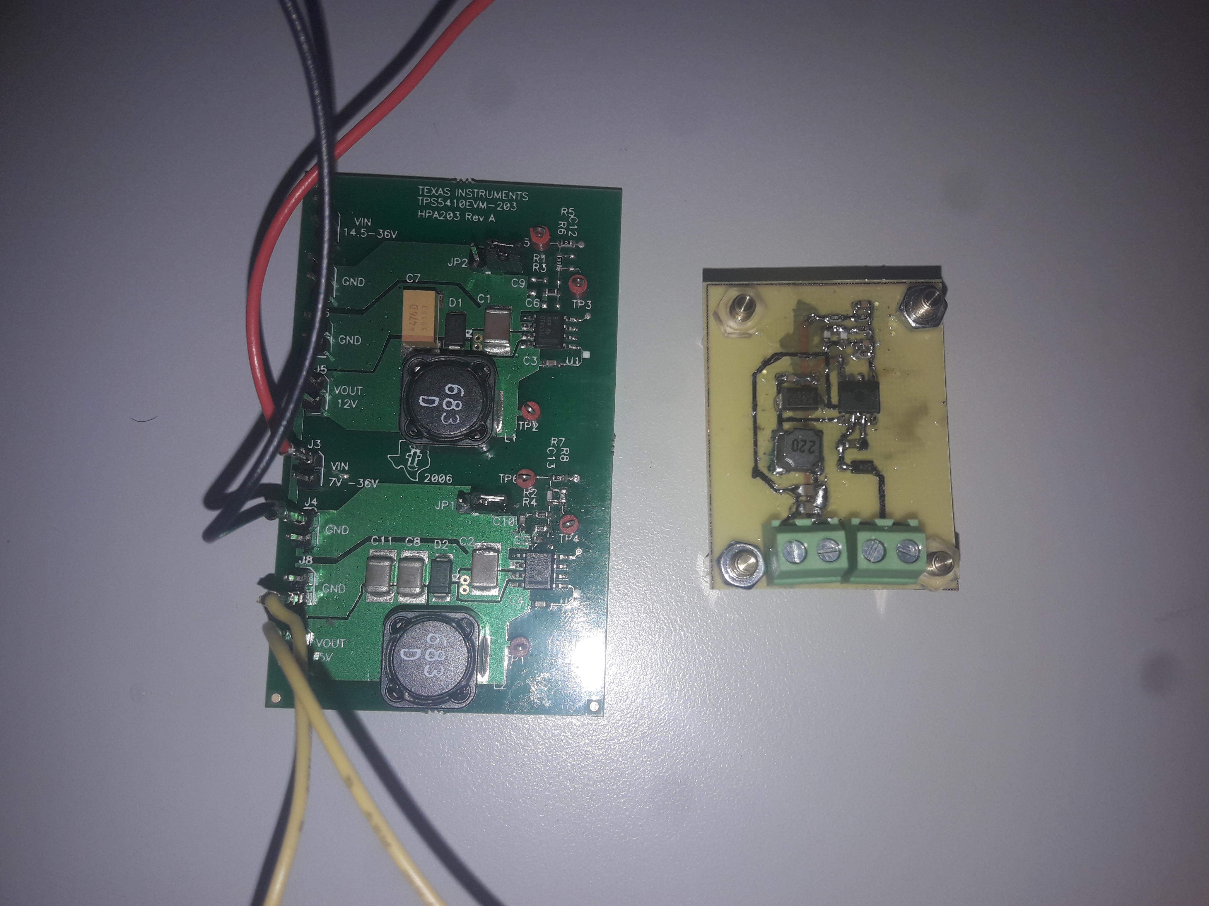
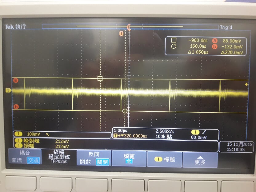
and I am compare the EVM board and my design board. when I measure and i don't use tip and barrel to measure and I didn't see high frequency like my post first picture.like green part 1.8Mhz.
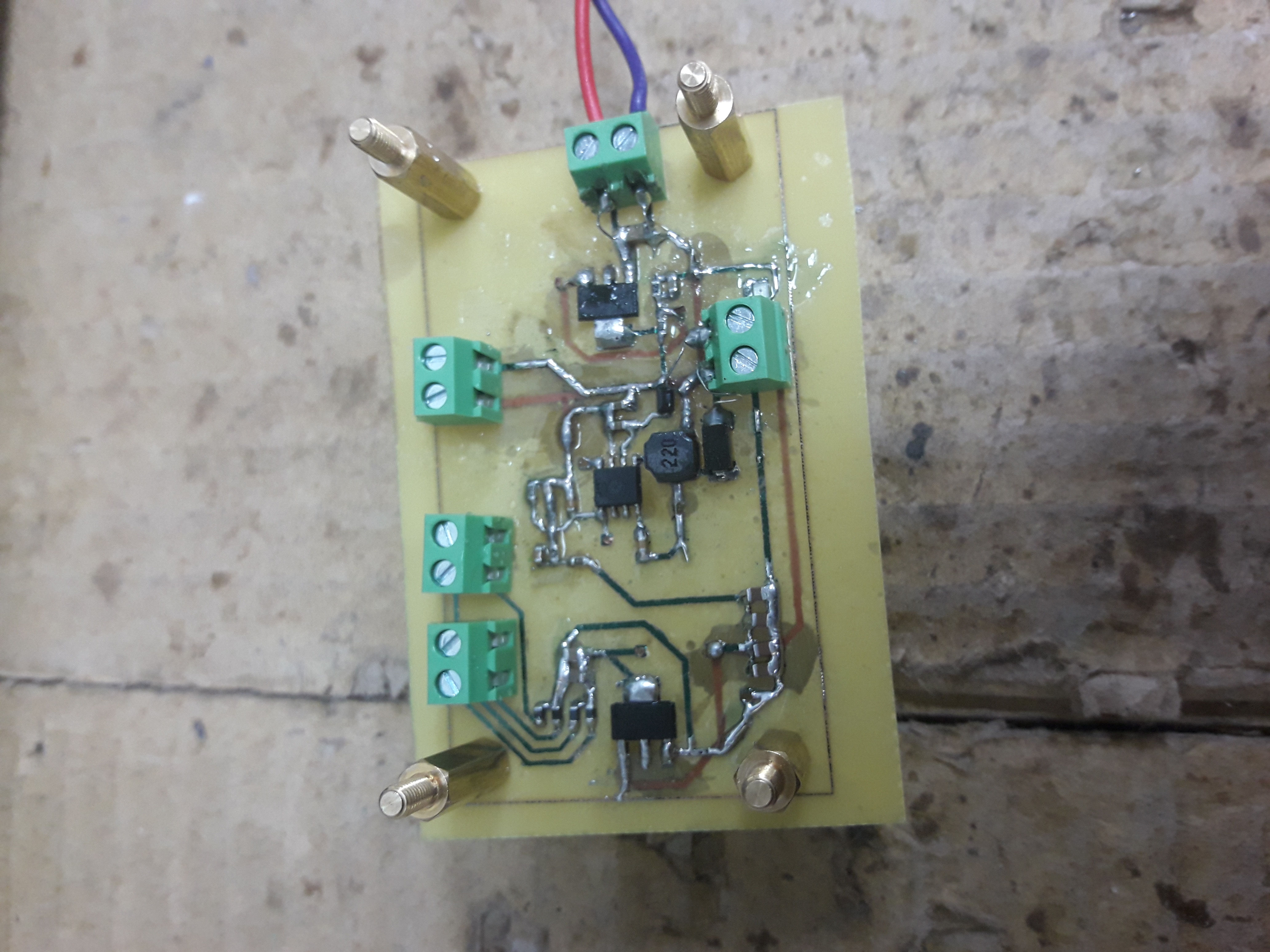
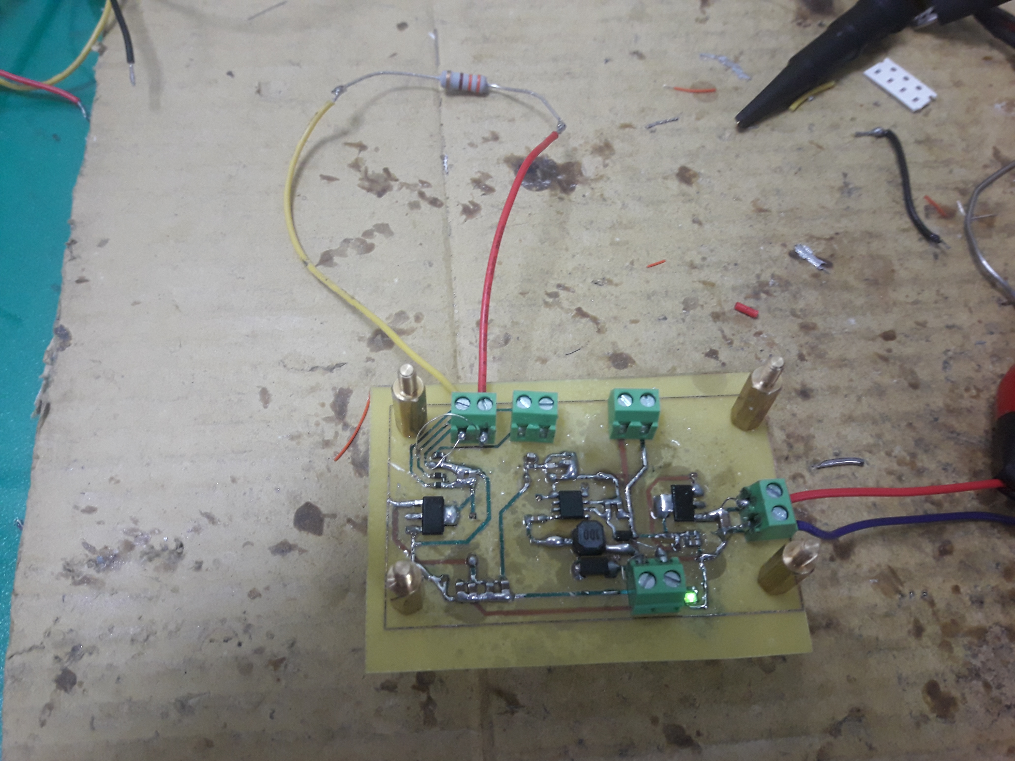
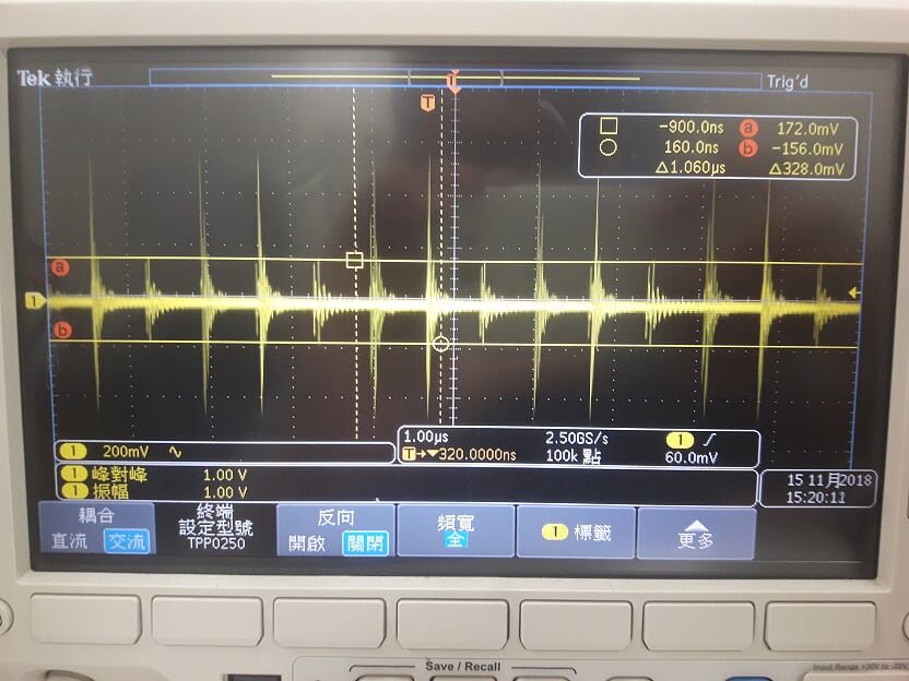
but i design board if i don't add R-load on 3V3D and 3v3Gnd the high frequency dose not appear. but if i and the low R-load (maybe 10ohm~30ohm) it will appear the 1.8mHZ. i have test for 10ohm,30ohm,and 330ohm, because my circuit R-load near to 330ohm so I add the 330ohm on my circuit.but it still can't resolved this problem . it appear on 330ohm for high frequency. as the same value of resistance on EVM . it also not appear.
so this is layout problem?
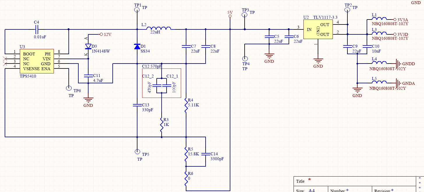
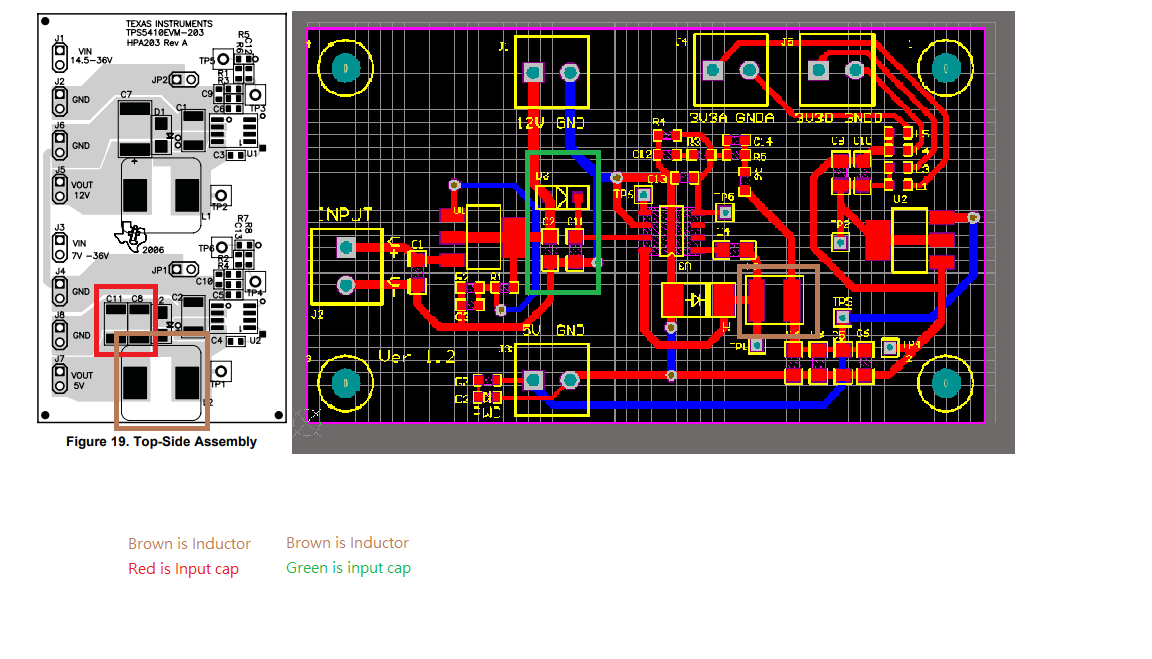
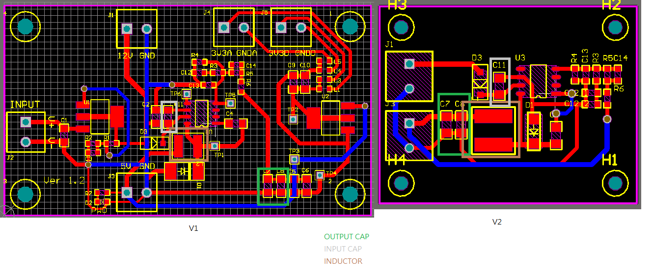
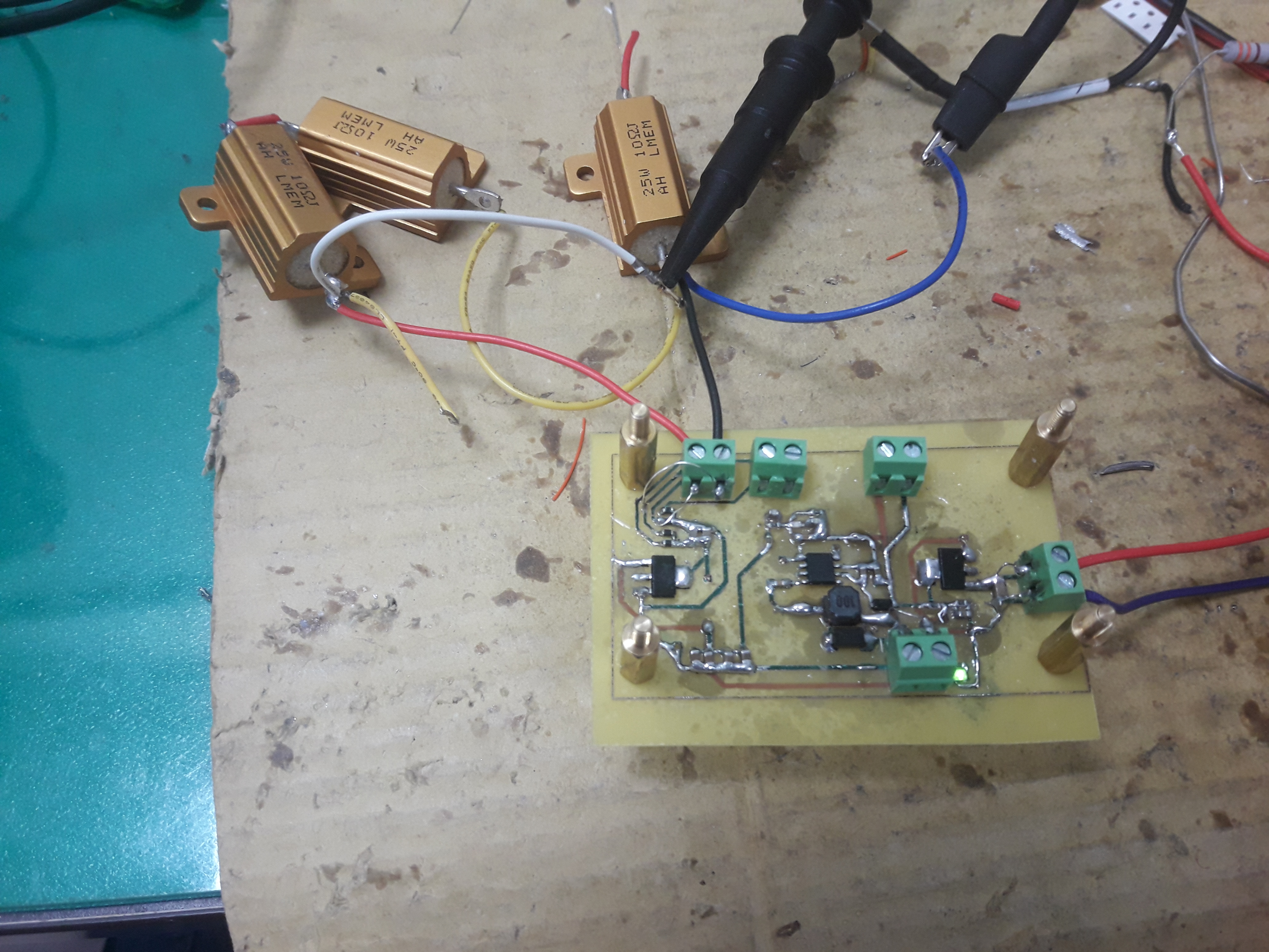
this is my layout picture, as u document file say that the input cap and inductor distance maybe cause HF noise.
it is 1.8mhz build reason??? So Other than this it only has improve layout to reduce noise or it
maybe has another method to reduce such change or add some circuit componet to solved?
In regards to the measurement method, you want to understand the true level of noise. The noise may be there, but it is important to understand the true level that you are trying to filter out. With a bad measurement technique, noise can couple to the probe and amplify the noise of the design.
Also, how are you adding the resistor? Is this directly on the board or through long wires?
I think it is very possible this is a layout problem.
Please see my recommendations for your layout:
1. Move C11 as close as possible to the device.
2. Add a ground plane across the entire bottom layer of the board and entire top layer of your board. This will improve the return path of all signals. And will also provide an improved design for dissipating heat.
3.The inductor, boot capacitor, and diode need to be in as small as loop as possible.
4. Move the output capacitors directly next to the inductor.
5. Follow the example below for routing your resistor divider.
Thank you for sharing this additonal information. Can you please clarify which board/design you are using for both scope waveforms.
I think that is important that you place the load as close as possible to the output (eliminate the wires as much as possible), and measure the output ripple at the output capacitor with the tip and barrel method. If you use the ground loop, this can pick up different noise at different times. In order to get a consistent measurement for accurate comparison, I recommend using the tip and barrel method at the output capacitor.
Also, when you spin this board, you will definitely want to pay attention to the input capacitor and output inductor. I would recommend that the output capacitor can be third priority, but you do not want to let this capacitor move very far in distance from the inductor.
Due to inactivity on this thread, I am going to close this thread. The thread locks after 30 days. If you have any additional questions or want to continue this discussion, please feel free to open a new thread.