This thread has been locked.

If you have a related question, please click the "Ask a related question" button in the top right corner. The newly created question will be automatically linked to this question.

BQ25703A: Charge controller ignoring input current limit

Part Number: BQ25703A
Other Parts Discussed in Thread: EV2400, BQ25710, BQ25703, BQSTUDIO

Hello, hope you are doing well,

I am working on a project which involves my micro-controller (nRF52) controlling the BQ chip directly over I2C with no fuel gauge IC. I have been able to write to, and read from the host controlled 'input current limit register' 0x0E. I have verified this by updating the charge current register to a low value, and then reading value of the 'input current limit in use register' 0x24. The value of this register is updating consistently with changes I make to the host controlled input current limit register.

I am confident I can read the registers of the BQ chip correctly because the values I have been reading for input current and vbus are consistent with the power supply I am using to charge the device. Once the register value is read my process is to shift, mask, scale, and add the minimum value to the value read from the register. For example, with a register value of 0x0100 corresponding to 100mA:

shift = 8

mask = 0x7F (should have no effect, included for consistency with other read values)

scale = 50

minimum value= 50

read value = 0x0100
shifted value = 0x01
masked value = 0x01
scaled value = 50
scaled value plus minval = 100

(there seems to be some ambiguity between the data sheet and Battery Management Studio as to whether 0x0000 should be interpreted as 50mA or 0mA, but this difference is much smaller than my error).


In practice, however, the BQ chip seems to completely ignore whatever value is set in either input current register.

I have tried two different power supplies: one has a settable current limit, the other current limit is simply 2 amps. When the settable power supply is connected and I place a heavy load on the power system the settable power supply goes right up to its current limit despite the BQ chip's current limit being set well below the supplies limit (2.5A limit on the supply with 500mA input current limit programmed to the BQ chip). The 2 amp power supply simply stops delivering current when the system is under heavy load, and all current is supplied by the battery until the heavy load on the system is removed.

I'm aware it's rather inelegant, but relying on the current supply limit of the power supply isn't the end of the world for my design. What I'm afraid of is someone connecting a power supply with a higher current rating that my input power path can support to this device. I would like the BQ chip to limit this incoming current to a safe amperage. 

  • Hello Tim,

    There is a setting in charge option register 2 (0x32) (at position 1 << 7) that is called "EN_EXTILIM."  By default at bootup, this bit is set.  When set, the ILIM specified by resistor divider on the ILIM_HIZ pin overrides the software ILIM set in register 0x0E. 

    Please clear this bit and let me know if it resolves the issue.  If not, can you provide me a little more data?:

    1.  What hardware are you working on -- EVM, your own hardware or both?

    2.  Can you capture your full register set using BQ "Save Registers" and send to me?

    3.  If using your own hardware, can you verify that ACP/ACN design follows section 10.2.2.1 of the datasheet and that RSENS_RAC value in register 0x30 matches the value of sense resistor chosen (10 or 20 mOhm)

    Thanks,

    Steve

  • Hello Steve,

    It's my understanding that the input current limit should be the lower of the external and register-defined input current limits. Either way, I have cleared this bit and and my device still draws more than the limit I set in the register.

    I am using a custom PCB. I am using a 10 mOhm sense resistor and have not modified the RSENSE_RAC value in register 0x30, which defaults to 10 mOhm.

     The charger board I am using right now is installed in a device which I can't easily access. The BQ chip's I2C lines are connected directly to my microcontroller and it would be very difficult to use the EV2400 to interface with my PCB. I'll get started writing a function to poll the BQ chip's entire memory and put it in a CSV or something. I have another board which is not installed that I can test, but we have been focusing on the assembled device recently, and it will take me a while to get the rig and other boards up and running.

    I just checked my hardware against the ACP/ACN design in the datasheet and it looks like I missed the 1nF+10nF capacitor between RAC and Q1. I will correct this in the next set of boards I order.

    -Tim

  • Hi Tim,

    You are right about the EN_EXTILIM bit. Since you are setting a lower value in the 0x0E register, it will take effect regardless of the setting of this bit.

    I think it is good that you are adding the 1nF+10nF capacitors, although I would be very surprised if this was the cause of your issue. A large DC current through the sense resistor should trip the ILIM without them.

    Can you use the ADC to take an I_IN measurement? You can use the following procedure (this should be correct, but I tested on a BQ25710 EVM and then translated the procedure to BQ25703 registers, which are slightly different, so please double check if you run into any issue.) :
    1. Clear bit (1<<15) in register pair 0x01/0x00 (Charge option 0) in order to exit from low power mode.
    2. Also clear bits (11b << 13) in register pair 0x01/0x00 in order to disable watchdog timer.
    2. Write 0x4010 to register pair 0x3B/0x3A, ADC Option Register (enables I_IN measurement, configures for one-shot and provides the ADC_START trigger.)
    3. Read register 0x2B/0x2A -- return value

    Also, a general question -- are you seeing the BQ25703 current limit at any level, even just with default values in the registers? If you have never seen BQ25703 current limit, what is the highest current value you have tested with. If you have seen it current limit, what value was in register 0x0E and what was the actual value that it current limited at?

    Thanks,
    Steve
  • Yes, I can read I_IN with the ADC and it corresponds with what my power supply reports (I'm using the 1-second period with the ADC, and I have the watchdog enabled and regularly fed).

    We only have one charger board in-system right now and I don't want to risk damaging it testing the current limit. I'll get back to you tomorrow when we are able to test with another system. The external voltage divider should be configure for a max input current of 3300mA, which is the value of the input current in use register after a reset.

  • Hi Tim,

    Just wanted to check in to see if you have been able to perform a register dump or if you have been able to measure the higher current levels to determine if there is a trip at any point.

    Since you are able to measure the current with ADC, this suggests that everything is fine with hardware. As we discussed there is some possibility of high-frequency noise that the ADC may not show, but the worst case that this noise should present would be to reduce the precision of the current limiting, not to remove it altogether. I don't think that noise could lead to the condition where you are setting a very low I_IN and not seeing it limit.

    Since the hardware appears to be in working order, I think that the next best step would be for me to load and exact capture of your register settings on the EVM and then test ILIM. I have mentioned all of the register settings I am aware of that could lead to the I_LIM not being applied, but it is possible there is something I have missed. Most definitive would be to load your exact settings and attempt to recreate here.

    Regards,
    Steve
  • Hello Tim,

    I have not seen any activity on this thread in about two weeks, so I am assuming that you were able to resolve your issue. I this is not the case, please provide the above requested information and re-open the thread.

    Regards,
    Steve
  • Hello Tim,

    I see that you have marked this issue as remaining unresolved.  Were you ever able to take a register dump from your system?  I will be able to load this onto an EVM on my side and verify if the issue is present.  At this point, I am still unable to recreate the issue, so I will have difficulty to proceed without this information.

    Thanks,

    Steve

  • Hi Tim,

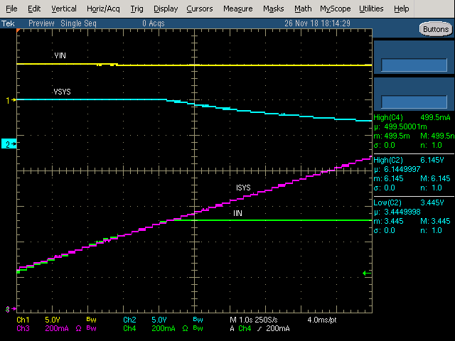
    Procedure:

    1.  5V on VIN

    2.  No battery attached

    3.  Jumpers configured for 2 cell

    4.  With BQStudio, disable Watchdog, set input current register = 600 mA

    5. Increased ISYS with CC mode Eload.  Scope capture attached

    6.  Using BQStudio, read IIn with ADC.  

    **Reads Back 500 mA instead of 600 mA as set**

    So I also see a discrepancy between the input current register and the measured input current limit, but the ADC is in good agreement with the scope capture and the input current limit register as reported by BQStudio is only off by 100 mA (I say "only" as compared to your case in which you are not seeing any current limiting up to 2A).  Also, as expected, I see the input current limit when 500 mA is reached, but the output current continues to increase.  This results in a voltage drop on VSYS. 

    So, while I do see the offset discrepancy you reported, I am unable to recreate your issue of no current limiting.  Can you tell me if my procedure above differs from your test scenario in a significant manner?  Perhaps you can provide me with your boards schematics or your register dump?  Clearly something is different in either hardware or register settings between the system I am testing and the one you are, but without this information I have no way to determine what that is and therefore no means of resolving the issue.

    Since issue cannot be recreated with the current information, I am going to mark the thread as resolved.  You may reopen by clicking the "this did not solve my problem" button.  This will reopen the thread as unresolved.  If you would like to reopen the thread for continued support, please include some of this requested information (register dump or schematics) so that I may try to determine what is different between our two systems.  

    Thanks!

    Steve