This thread has been locked.

If you have a related question, please click the "Ask a related question" button in the top right corner. The newly created question will be automatically linked to this question.

Any ideas why this chip only outputs 10.8ma total instead of the 120ma it should?

Part Number: TPS61177A

Hi Folks,

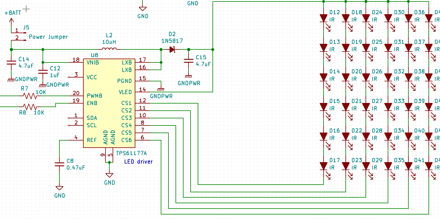
I'm working with the TPS61177A LED driver chip in a prototype and I'm running into a strange problem.  As the thread title above states the chip isn't putting out the expected current.  I'm measuring the current at the cathode side of D2. I'm not using the I2C features so the chip should default to 20ma per CSx right?  The voltage at D2 looks correct at 11.87V.  I'm not 100% certain that the chip is soldered correctly since this is a prototype that I soldered in our small reflow oven.

Does anything jump out as wrong?  I'd rather not re-do another board but if the schematic looks OK I guess that's the only thing left.

Thanks in advance,

Richard

  • Hi Richard,
    Your schematic seems ok. The default current is 20mA per channel. Looking for your good news.
    Best Regards
    Sean
  • Hi Sean,

    Thanks for checking my design.  I do have some good news.  I replaced one of the TPS61177A chips and now it looks like the circuit is working.  I'm able to get 120ma at the cathode side of the diode.

    I do have a few questions for you. First is, should the chip output the max current with a PWM input of 100% duty cycle?  I'm asking because if I send the chip 100% the current falls to around 12ma.  If I send it a PWM signal of approximately 99.9% the chip goes into max mode and the LEDs get the full 120ma.  The PWM frequency is 1KHz.

    Second question - Our application will have the LEDs on a flex circuit which means at worst case some of the LEDs in the array might be 5" -6" away from the 61177A chip.  Do you think that will be a problem?

    Thanks again,

    Richard

  • Hi Richard,
    Thanks for your good news. Yes, TPS61177A should output maximum current with 100% PWM duty cycle. Since your phenomenon is a little odd, can you measure what's the difference at the "PWMB" pin when you change duty from 99.9% to 100%. Does this orrurs every time when you change duty from 99.9% to 100%?
    For the flex circuit, I think you may add a litter higer value capacitor at the output pin. Thanks.
    Best Regards
    Sean
  • Hi
    I'll close this thread due to inactivity and if you have more questions please reply to it directly and it will open again. Please help to click "Resolve" if the problem is solved.
    Regards
    Sean