This thread has been locked.

If you have a related question, please click the "Ask a related question" button in the top right corner. The newly created question will be automatically linked to this question.

WEBENCH® Tools/LM3481: The design of a boost circuit does not work

Part Number: LM3481

Tool/software: WEBENCH® Design Tools

Hello,

I design a 24V to 60V boost circuit for my project with WEBENCH Tools. However, it seems not work. The layout of PCB is the same as datasheet.

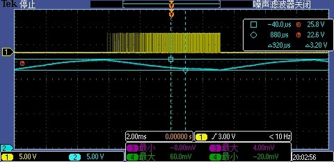
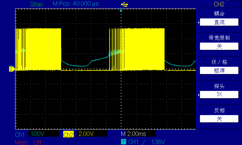
This is the waveform of the circuit. The yellow line is the voltage on MOS gate and the blue one is the voltage on COMP pin(output of error amp).

It is strange that the MOS is alway closed at some time. The datasheet says:

"At the start of any switching cycle, the oscillator sets the RS latch using the SET/Blank-out and switch logic
blocks. This forces a high signal on the DR pin (gate of the external MOSFET) and the external MOSFET turns on."

I am confused. Is this chip broken?

Thank you very much.

This is my design:

WBDesign24-60.pdf

  • Hi,

    Thank you for choosing the LM3481. Can you take a zoomed-in scope shot of VCC, ISEN, UVLO, switch node, and output voltage?

    Best,
    Richard

  • Thank you for your reply.

    I have little experience in design and debug such kind of circuit. Your reminder is useful. I think I find the problem. The input capacitance is too small and it cannot start up because the voltage drops too much on Vin.  I never doubted the Vin voltage cause I use a DC power supply to power it. The wire between the circuit and the supply is about 0.1 ohm. I add the input capacitance to about 620uF and it start up quickly. I still notice that its voltage will drop at first but will become stable very quickly.

    Actually the whole design is 7V to 24V to 60V, two stage boost up. The second stage will share the capacitance with the first one. Can you give me some suggestions about the capacitance. Thank you very much.

    P.S. The ESR is less than 20mohm (Aluminum solid capacitance)