This thread has been locked.

If you have a related question, please click the "Ask a related question" button in the top right corner. The newly created question will be automatically linked to this question.

bq24630 low charging current

Other Parts Discussed in Thread: BQ24630

Hi

I have made a charger for 4 cell Li-FePo battery and its charging current is very low (14 mA). If I understand correctly the charging current should be 3 A (I have 100 kOhm and 22.1 kOhm resitors for the ISET1).

The changes that I have made when comparing the typical system schematics are (Schematics 2642.PPM_BatteryModule.pdf):

- I had to change the mosfet SI7617DN to another mosfet SI7121DN and the only difference I can see is 35V, 35A of the SI7617 to 30V, 16A of the SI7121.

- I don't have thermistor, but I have fixed resistor of 2kOhm and 3kOhm for the TS pin.

- Vin is 15 VDC. I have limited the adapter current to 6A with 100kOhm and 56kOhm resistors.

Can these changes be the reason for the low charging current?

I also have another question. While I was charging a battery that had very low charge (6 V) both of the status leds (STAT1 and STAT2) and the power led (PG) were on. I didn't find a state for this kind of status from the manuals table 3. What does this indicate?


Mikko Remes

  • I don't figure out why it 14mA yet. Would you help measure TS pin, ISET1, ISET2, ACSET, battery and input voltage for me?

    But, 15V input source is a little bit low to charge 4-cell Li-FePO4 battery. Adaptor voltage could have error. There is voltage drop on input FET also.

    I don't think STAT1, STAT2 and PG should be on together. I think some pins are blinking. It is very important clue. Please use sope to check which pin is blinking.

  • Hi


    Thanks for the fast reply. I tried to use different voltages in Vin. When I used 22V the charging current was 40 mA. I tested the TS, ISET1, ACSET pins and they had the right voltage (I don't remember the exact values, but i will measure them tomorrow). One battery had 12.2V and another had 13.3V while I measured the charging current. I have been charging the first battery for two days now (from 6V). There also was an misfortune with the batteries. While we were disconnecting the batteries from the old system we accidentally connected the plus and minus.

     I will measure all the values again tomorrow when I get to work. And also look the leds if they are blinking


    Mikko Remes

  • Good morning


    I have now measured the voltages. I first measured with the 15 V

    Vin = 15.08 V                        

    Vbat= 13.37 V,  Ibat = 6 mA

    TS = 2.004 V

    ISET1 = 0.612 V

    ISET2 = 0.306 V

    ACSET = 1.196 V

    I tested the voltages with the 21 V too and with another battery

    Battery 1:

    Vin = 21.04 V

    vBat = 13.38, Ibat = 31 mA

    Battery 2:

    Vin = 21.05 V

    Vbat = 12.81 V, Ibat = 34 mA

    Other voltages were the same as in the first measurement.

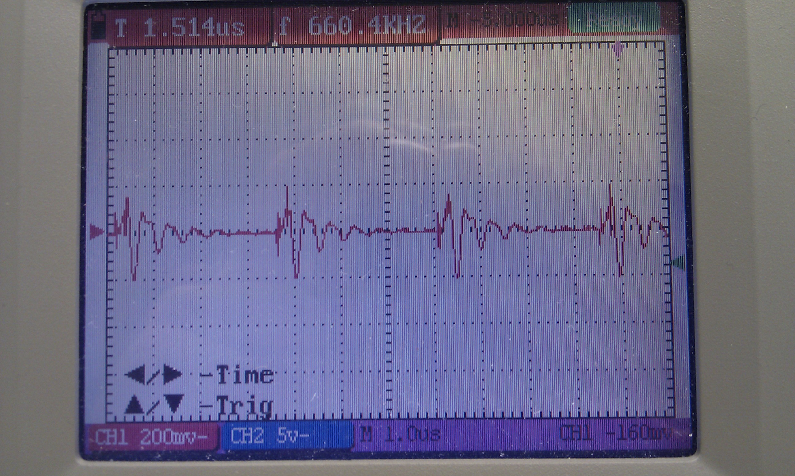
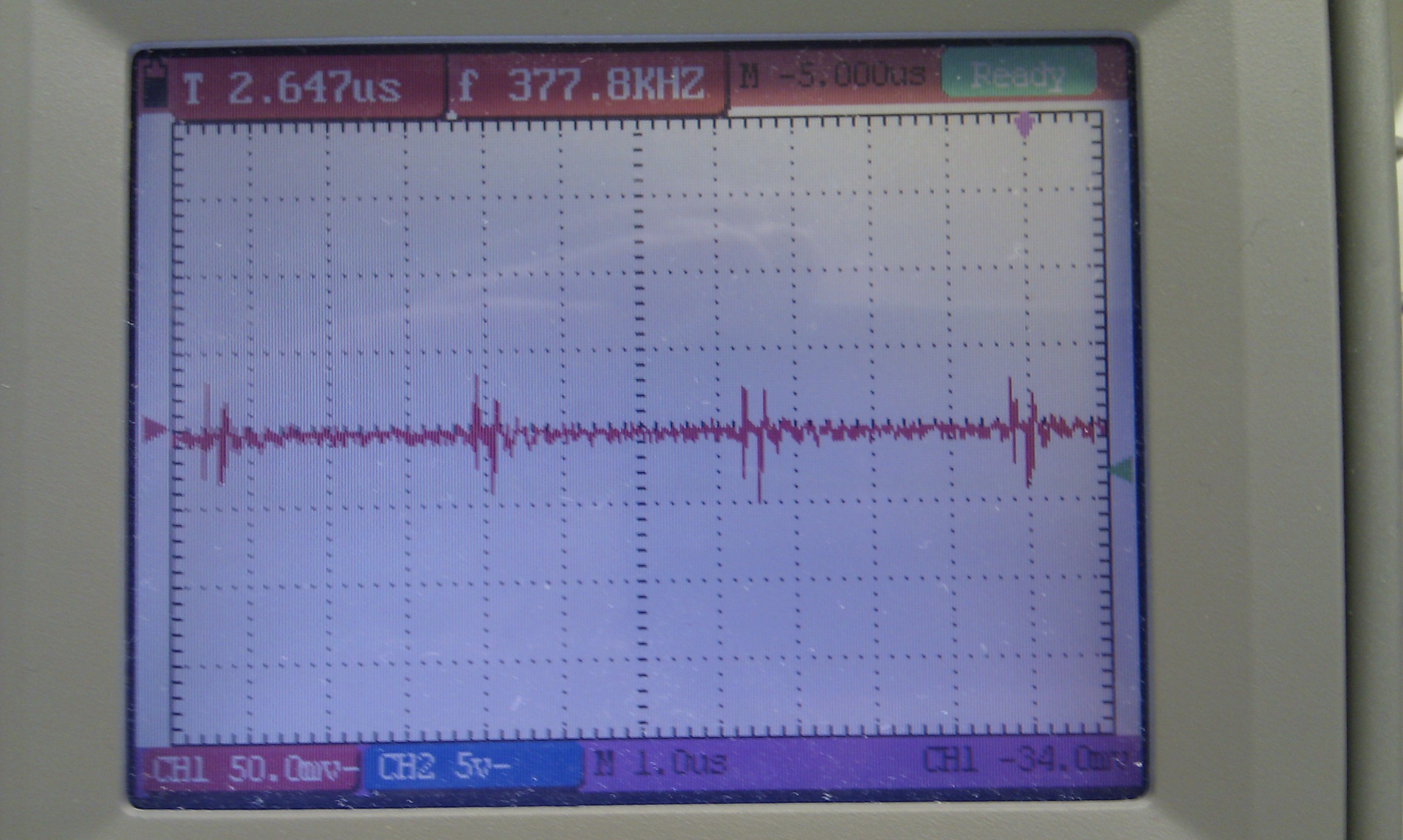
    Only two leds (STAT1 and PG) are on now and either of them doesn't blink. Thou there is a small spike in both every 3 microsecond. The third led (STAT2) seemed not to be as bright as the others, but I can't recreate this state so I cant measure if it is blinking or not.

  • Hi again


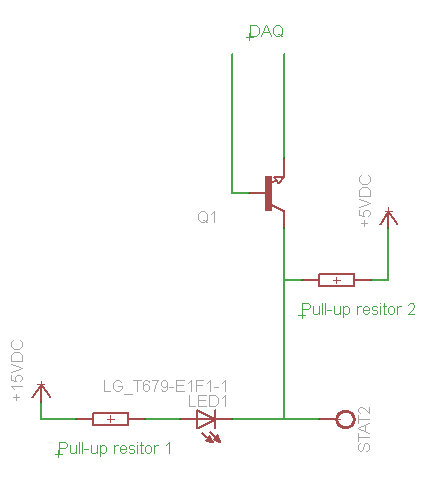
    I found out why the third led was lighted. I have a transistor that lets the DAQ know what status leds are on. There is a pull-up resistor for the transistor and it is pulled to +5V while the led is connected to +15V. The transistors are on a differend PCB so I will put some diods between the boards. that should fix the led problem.


  • If STAT1 is on, it indicates "Charge in progress". Would you hlep me measure the Vsrp-srn and Vacp-acn?

    In normal temperature range, the bq24630 should regulate the charge current at setting value. If the sense resistor has problem, it can cause a lower current.

  • Hi


    There does not seem to be any voltage difference between SRP-SRN or ACN-ACP.

    Vsrp-srn Vacp-acn

    Although there seems to be very small pulses between the pins (0.4V and 0.1V).


    Mikko

  • I didn't find any problem yet. Do you have a bq24630 EVM board? Could you do some tests on an EVM?

    Thanks

  • Unfortunately I don't have the EVM board. My PCB-boards were on tight schedule and we didn't have time to order EVM.


    Mikko

  • In this case, if you still need one to figure out the problem, please order it from estore. Or send your board to me. I can take a look in the lab.

  • Hi


    I just ordered a new board and I will test it when it arrives. It might be that the bq2430 has been damaged during the shouldering process. If the problem still exist I think I will have to buy the EVKit to get some more experience or send the PCB to you. Either way I will keep you up to date.


    Mikko

  • Hello

    I just received the new board and it doesn't work either. Can I send the board to you so you can test it or do you know any manufactors that make these kind of boards  so we could buy one? We only need board that has connectors for Vin, Vbat (4cell Li-FePo; 13.4V) and Vsys. Should be an easy board to make, but it seems that we don't have enough expertise to make one.

    Mikko Remes

  • The EVM default setting is 18Vreg (5cell*3.6Vreg/cell) LiFePO4 battery, to charge your 4cell battery, you need change the resistor divider R25/R28 on EVM--- VBAT = 1.8V × [1+ R25/R28]. And make sure VTS is in the range of (1.58V-2.33V) for fast charge. Please check the user's guide and d/s for detail.

  • Hi

    The new board that I mentioned was my designed board not the EVM. But thanks for the information. At the time being we will use external charger for the batteries. We will probably order the EVM someday and try to figure out how to make our charger board work.

    Mikko Remes

  • If you can share your schematic and layout, we can review it for you.

  • Here is the shematics and layouts. The project is designed with Eagle, also the layout is in gerber files and the schematics are in PDF. 7701.BatteryModule.zip

  • From the schematic I did not see any obvious problem except that the PGND and AGND are not separated (check the EVM and d/s for design and layout reference). Although I can not open the Gerber file to check the detail, I know some similar problems happened on other customer's application.

    1) Please verify the resistor R3/R8 are good, still 0.01Ohm.

    2) Please measure the voltage across R3 and R8 and that voltage directly at ACP-ACN and SRP-SRN pins of IC. Because the ground is not separate, noise will be introduced to the current sensing loop (note normally this voltage is 10mV level). C5/C10 ground is AGND and all C5/C10/C4/C7 need to be placed as close as possible to IC pin.

    3) check the VCC_BAT voltage to make sure the IC is powered (R4 is not burned), check the REF and REGN to make sure the LDOs work. Check TS/ISET/ACSET voltage make sure the resistors are installed right.

    4) check the SYSTEM voltage to make sure input FETs are ON and buck converter has input.

    5) check the PH/BTST/HIDRV/LODRV waveforms to make sure the converter is switching.

    6) check the VFB voltage (this sensing loop also sensitive to noise, check the EVM for layout). It's should be 1.8V at voltage regulation.

    If you still can not fix the problem. Call us and ship your board to us to check it.