


Tool/software: WEBENCH® Design Tools
Hi,
I am trying to design a DC-DC converter capable of sourcing 12A at 2.1V with a 4-13V input. My design is based on TI’s WEBENCH web app using TI’s LM27402. The output design from WEBENCH is below.
I did some modifications to the design from WEBENCH and the final schematic is below.final_schematic.pdf
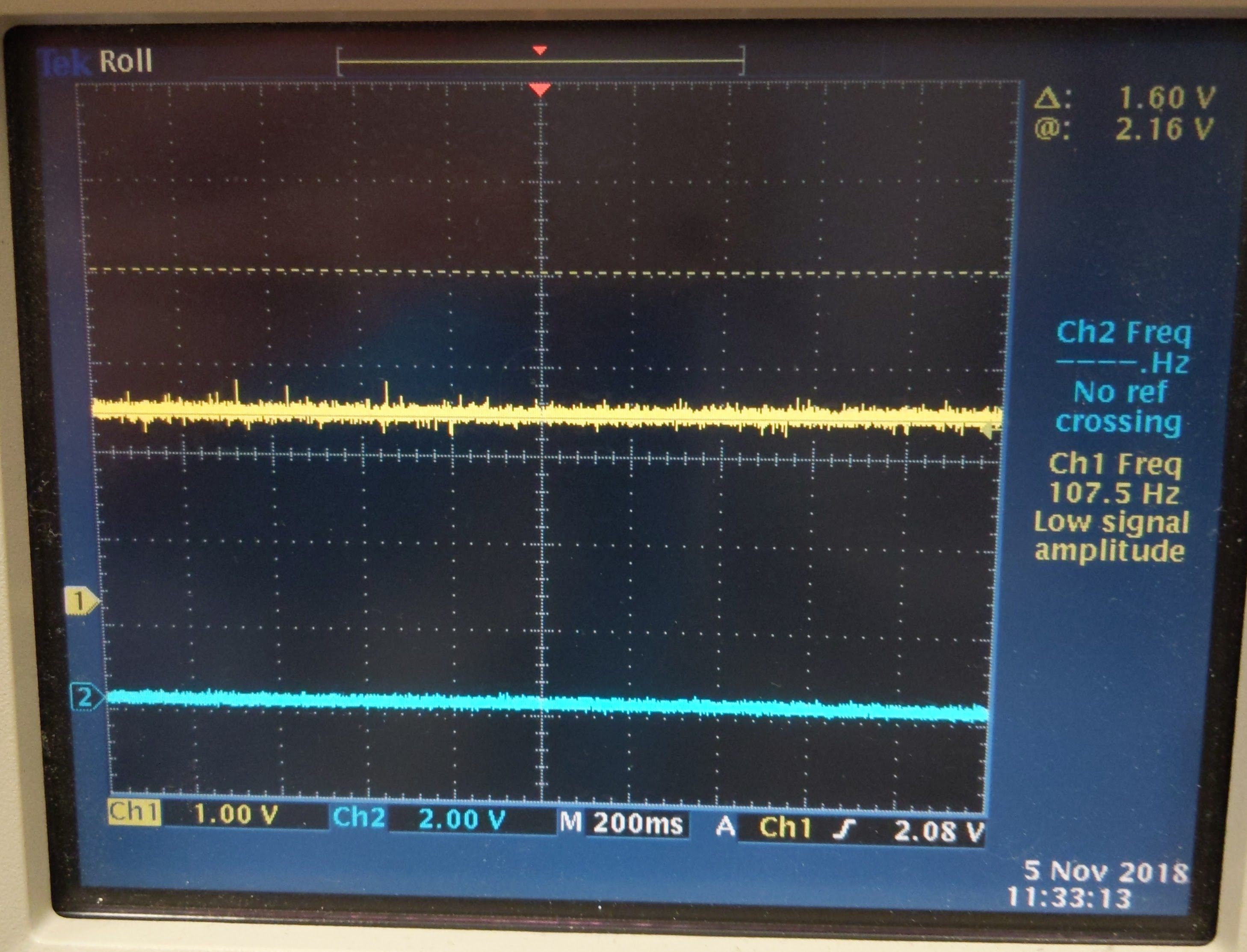
When bringing up the circuit we saw our designed 2.1V with a power good signal. I probed the output with a oscilloscope and the result is below (output_1.jpg) where channel 1 is the output.
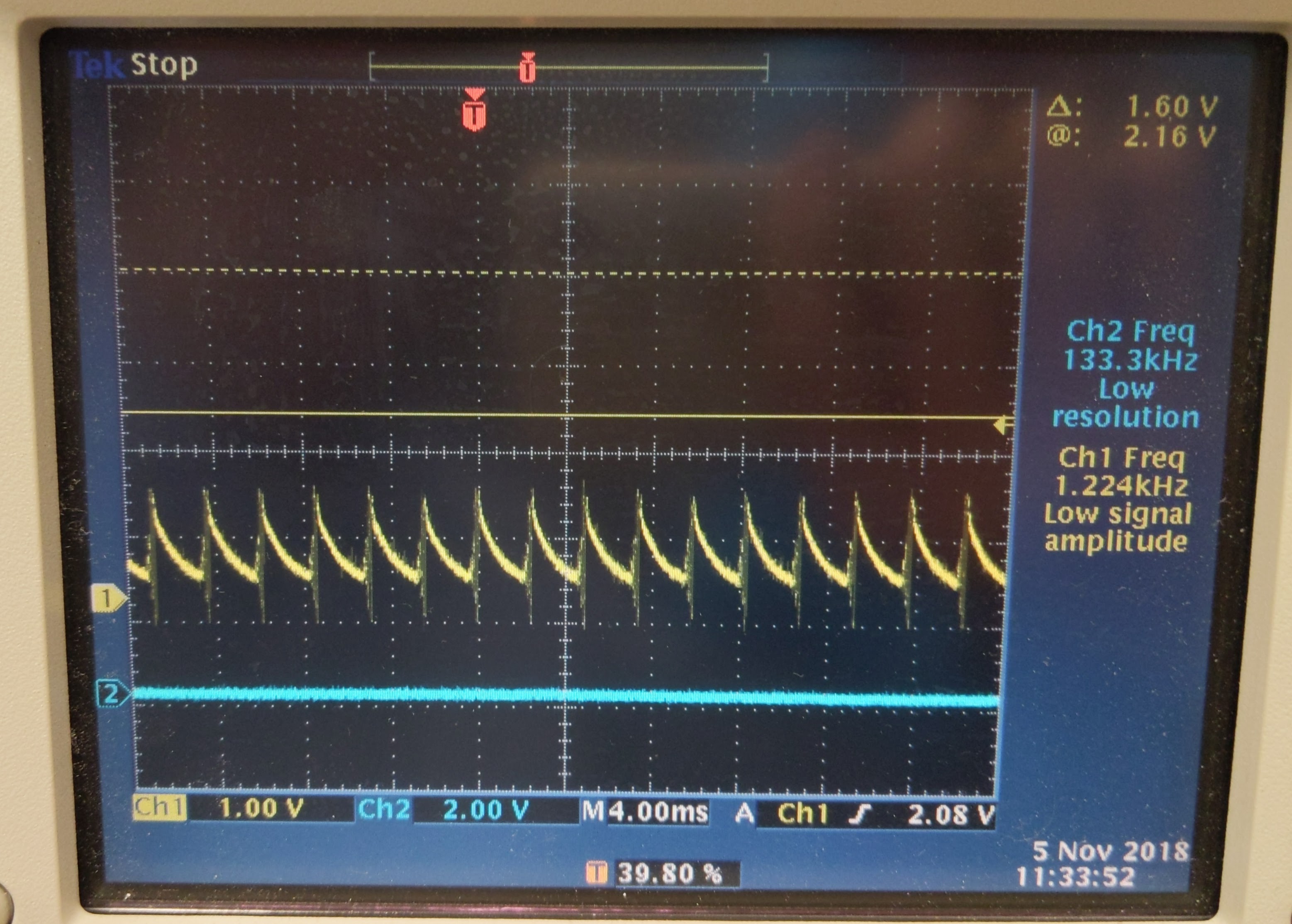
Then I applied a 1 ohm load to see how the output would change. The result (output_load_1.jpg) shows that the LM27402 went into some sort of hiccup mode of periods of switching and rest.
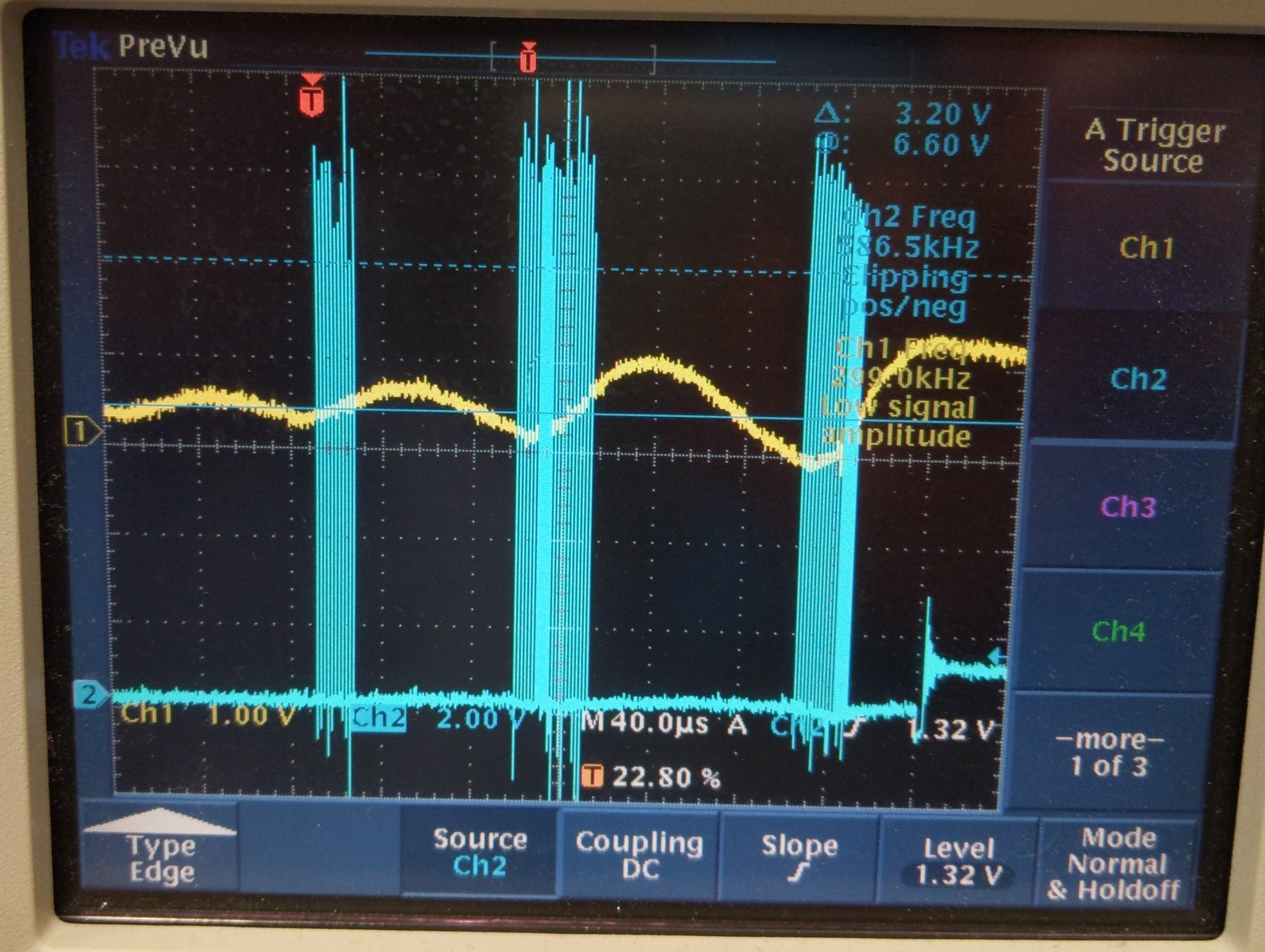
Further zooming of the signal (output_load_2.jpg) shows that when the buck converter stops switching (where channel 2 is the signal seen on the SW pin), the low side MOSFET is turned off, indicative of an overcurrent event as demonstrated in the datasheet Figure 25.
The issue is that when calculating what our current limit should be, I get around 17.5A using equation 13 from the datasheet.
One issue I thought of is that the time constants with the DCR of the inductor and the RC filter are not matched. Using the 3.43mohm DCR of our inductor, we should be using a 901 ohm resistor for R_S using equation 12 in the datasheet. I am using 845ohms. Could R_S really be that sensitive?
I tried changing R_SET used for setting the current limit and observing the output. The observations are below:
|
R_SET (ohms) |
V_OUT |
Power Good |
Notes |
|
3.7k |
1.82V |
0 |
Unstable output |
|
5.1k |
2.0V |
0 |
Unstable output |
|
10k |
2.08V |
1 |
Source < 330mA before entering hiccup |
|
16k |
2.08V |
1 |
Can just barely source 330mA. Needs some sort of load to achieve designed output voltage. |
|
>50k |
1V to 5V |
N/A |
Unstable output going from overvoltage event to undervoltage event |
Would anyone have an idea of what is going on? I am happy to provide any information/data necessary for your analysis. I hope to hear from you soon.
Warm Regards,
Nick
