This thread has been locked.

If you have a related question, please click the "Ask a related question" button in the top right corner. The newly created question will be automatically linked to this question.

LM2841: FB pin

Part Number: LM2841

Hi

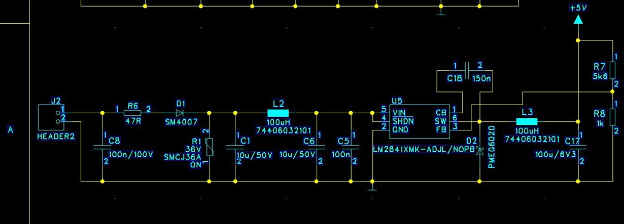
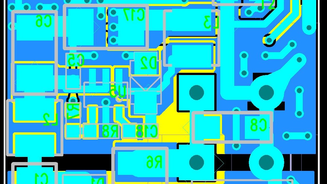
We have a design with the LM2841XMK. It is set to produce +5V out of +24V. The lower feedback resistor, 1k, size 0603 is directly located at pins 2 and 3. The upper one, 5k6, is located very near too. All EMI tests went very well. We use formal coating to protect the PCB. Now we noticed that when water is applied to the place where the chip resides the output voltage drops. Even condensed water shows the effect. It is more, when the input voltage increases and less with lower input voltage. So we think that there is a capacitive coupling from the switching voltage to the feedback pin, which let the voltage drop. Do you think a small capacitor of some pF over the upper feedback resistor could help to make the feedback loop less sensitive. Or do you have any other ideas? Thank you for your time.

Gerhard

  • Hi Gerhard,

    Are you also getting water on the feedback resistors? I am wondering if the top feedback resistance could be changing.

    Can you share the schematic and layout as well?

    Best Regards,
    Katelyn
  • Hi Katelyn,

    thank you for replying.

    I am very sure that there is no water directly on any pin as the complete circuit is under a varnish layer or formal coating. I am not sure about the correct English word here. However there is water directly on the varnish above this resistors. I made a test where I put the PCB in the freezer and after a few hours I connected it to a power supply while having the output voltage on the scope. I saw the voltage drop from 5V to 4.3V while water condensed on the surface. After a few minutes the voltage rised to 5V again while the PCB was drying.

    The schematic is as on page 13 of the data sheet with an inductor of 100uH and a ceramic capacitor of 100uH (X5R). As I am at home now and not in the office I cannot share the layout.

    Best Regards

    Gerhard

  • Hi Gerhard,

    When you have a chance, could you share the schematic and layout?

    Also, does the DC output voltage drop, or is the output voltage oscillating?

    Thank you,
    Katelyn
  • Hi Gerhard,

    take a tiny aluminium foil snippet and move it to the place where you have observed the condensed water making the output voltage drop. Try to introduce some capacitive coupling with the foil snippet. Do you see now a voltage drop? Don't take a screwdriver or anything else containing ferrous materials because this can affect the inductance of your 100µH coil.

    Unexpectedly paralleling the upper feedback resistance with a capacitance might not be a good idea because this can alter the phase response within the feedback loop and decrease the stability of LM2841.

    If you expect greater amounts of water you should consider encapsulating the whole circuit in potting compound instead of applying only a thin layer of coating. This depends of course on the heat dissipation of your LM2841 circuit. You could also shield the circuit before coating or encapsulating, if the capacitive coupling issue persists. Connect the shield to GND.

    Kai

  • Hi Katelyn,

    the voltage does drop, there is no oscillating. In the mean time we have made some tests with 33p on the upper, the lower and on both feedback resistors, but without any effect. Same result with 180p on the upper resistor only.

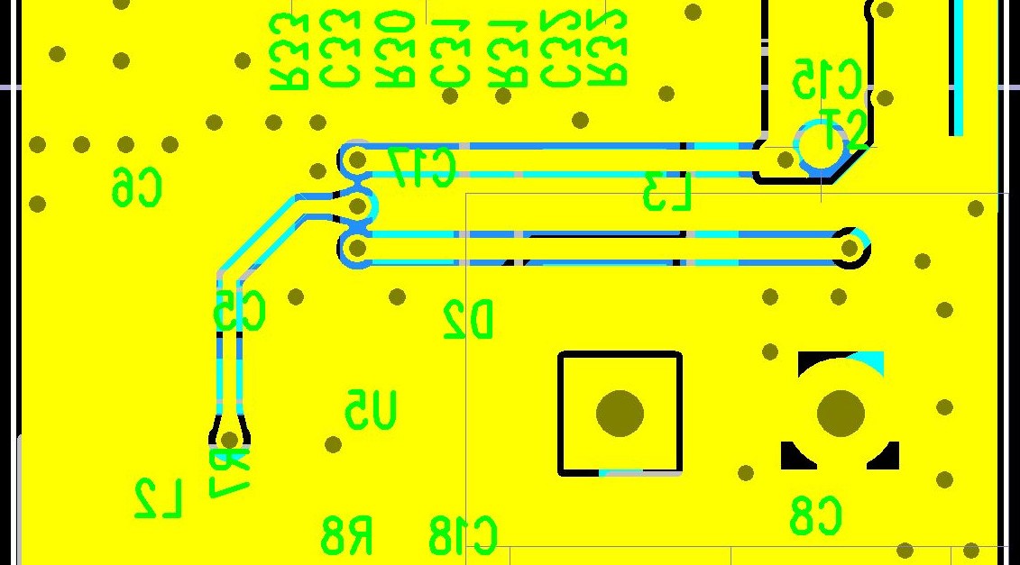
    Here are drafts of the circuit and the layout. Parts are on the bottom layer, top layer is all GND here.

    Regards

    Gerhard

  • Hi Kai,

    Thank you for your reply, your idea testing with a foil snippet sounds interesting. I will do some tests. We have also made tests with some epoxy on that parts and the effect went away. When I tip with a screwdriver on the different parts of the circuit I don't see a voltage drop.

    Gerhard
  • Hi Gerhard,

    so, when using epoxy the capacitive coupling issue is solved? No more voltage drop?

    Kai
  • Hi Gerhard,

    Thank you for sharing your schematic and layout. How are the signals routed through the two vias which are connected to the feedback resistors?

    I agree with Kai that if the feedforward capacitor will effect the stability and may not fix this issue. I believe this problem is related to the coating the coupling as well.


    Thanks,
    Katelyn
  • Hi Kai,

    sorry for my delayed response, I am also occupied by other projects.

    I would not say that it is solved by the epoxy, even if the drop has disappeared. I think the effect is masked and we would like to understand in more detail what is going on here.

    Last Friday I was able to test a module with a small piece of aluminum foil. I moved it around where the chip is soldered. The effect which took place took only a short period of time. I saw the voltage on the scope moving down and up again for a few times and then suddenly the output got stuck on 2V. The LM2841 seems to be defectives now as it does no more switch its output pin.

    We have now prepared a module with a thin wire on the feedback pin under the formal coating and I will put this signal on the scope while applying water to it. I hope I can perform the test tomorrow.

    Gerhard
  • Hi Katelyn,

    Here you can see on the top layer how the signal is routed from the 100u output capacitor to the top feedback resistor. The other two horizontal routes feed from the output capacitors loads in the rest for the circuit.

    We are aware of the fact that a capacitor on the feedback resistors has an effect on the stability. But we thought on the other hand, that a sufficient small capacitor could compensate the capacitive coupling of the high speed switching signal into the feedback pin as it should work like a short circuit for high frequencies. I hope I will know more tomorrow when I have done the tests as mentioned to Kai.

    Thank you,

    Gerhard

  • Hi Gerhard,

    Thank you for sharing the layout. The feedback trace looks good, as it is routed away from SW.


    For the CFF, this component can help, but it will depend on the value and cross over frequency of your system. Below is an app note which discusses the CFF choice is more detail.
    www.ti.com/.../slva466a.pdf

    Best Regards,
    Katelyn
  • Hi Gerhard,

    I want to follow up on this E2E thread. Were you able to do additional testing? Did you solve this issue?

    Best Regards,
    Katelyn
  • Hi Katelyn,

    Hi Kai,

    when I displayed the FB pin on the osci I observed small rectangle pulses when I applied the water. Then we soldered 1n on the 1k and 180p on the 5k6 feedback resistor and the rectangle changed to a triangular waveform. With the rectangle and triangular waveforms we could only observe small influence on the output voltage. As we applied the water with a Q-tip now we could probe more precisely.and found a place for the Q-tip where the output voltage drops very much. But the FB pin didn't show any change then. It seems that from the input voltage current is coupled into the bottom feedback resistor, which let the output voltage drop. We think both observations can only be explained with a galvanic coupling. Hence our focus is now on the process of how we apply the formal coating.

    Thank you both very much for your time!

    Best Regards

    Gerhard