This thread has been locked.

If you have a related question, please click the "Ask a related question" button in the top right corner. The newly created question will be automatically linked to this question.

BQ25700A: Need some support for their software team in understanding in how to talk to this chip over the SM bus

Part Number: BQ25700A
Other Parts Discussed in Thread: EV2400

Hello team,

Hope you are doing well. When you get a chance can you help with how to interface with BQ25700A via SMbus. Customer is following below steps:

1. You can leverage IO Space to read and write 0xE300

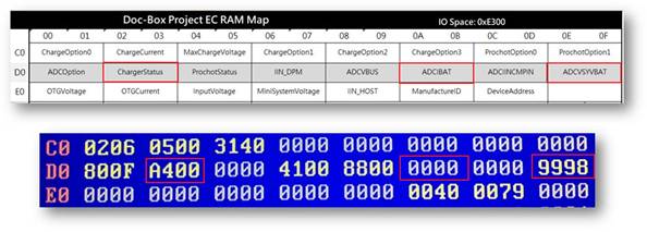
Charger Status Reg[0xD2], bit 15,0 (AC Input not present) / 1 (AC Input is present)


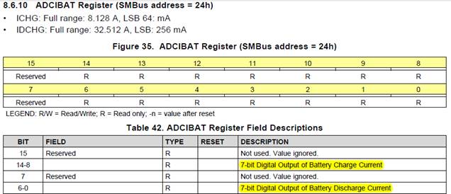
ADCIBAT Reg[0xDA], Bit 14-8, if it’s under charge mode,it will show charging current.

ADCIBAT Reg[0xDA], Bit 6-0,if it’s under discharge mode,it will show discharging/drain current.


ADCVSYSVBAT Reg[0xDE],BIT 7-0  is able to read the current of  battery charge/discharge.


Regards,

Randhir


  • Hi Randhir,

    From the above, I believe that your customer has verified that they can correctly read and write registers over SMBUS, but is not getting the expected value for ADC reads. Is this correct? If so, the below is a full procedure for reading V_BATT which is easily extended to the other ADC reads:

    Procedure to read V_BATT using EVM and EV2400:
    1. EVM jumper J2 is on, and J3, J4 jumpers are off (2-cell)
    2. Attach 100,000 uF capacitor and bipolar CV power supply at J5, power supply set to 7.4V
    3. Power on board with 5V at J1
    4. Write 0x000E into register pair 0x01/0x00
    This turns off the watchdog timer and takes the device out of low power mode. Note datasheet description of EN_LWPWR bit in section 8.6.1.1, "ADC is not available in low power mode."
    5. Write 0x6001 into register pair 0x3B/0x3A
    This enables the ADC in one-shot mode, enables the VBATT read and sets the ADC_START trigger bit.
    6. Read register 0x3B/0x3A pair
    it should return 0x2001, which is the value that was written but with the ADC_START bit cleared, indicating that the ADC has run.
    7. Read register 0x2D/0x2C pair
    it returns 0x0046, which is a value of 7360 mV for V_BATT. V_SYS is zero'ed because its bit was not set in step 5


    A common step to miss is #4 -- often people do not know that the ADC will not work when in low power mode.

    If the above does not resolve the issue, then please provide more detail on which point in your customer's procedure they are having difficulty-- i.e. the exact step they are seeing a failure, what is their expected result and what result are they getting instead.

    Regards,
    Steve