This thread has been locked.

If you have a related question, please click the "Ask a related question" button in the top right corner. The newly created question will be automatically linked to this question.

UCD3138: UCD3138 Successive Approximation Mode issue

Part Number: UCD3138

Hi Sir:

We are using FRONT END 0 (EADC and DAC together) in Successive Approximation Mode, while we found some timing issue;

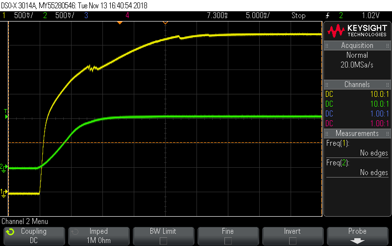
when there is bias voltage(around 1V) on EAP0/EAN0 before or during V33 rising, the final SAR calculation is always zero, do you know why? if the bias voltage is unavoidable how to use SAR under this condition? thanks a lot;

waveform is attached; CH1:V33, CH2:EAP0/EAN0;

thanks a lot;

  • more information here
    1\when we change V33 to rise faster,like in 2ms to 3.3V, while keep EAP0/EAN0 the same rising time and voltage level, the reading is still zero;

    2\while if we reduce the EAP0/EAN0 voltage level a little, the reading is right;
  • It is very dangerous putting voltages on pins when the UCD V33 is zero.  It's out of the device spec.  You can end up powering various circuits.  You're lucky that the processor starts up and only the SAR is not initialized properly.  Maybe try a clamping diode and a small series resistor to keep the voltage closer to V33? 

  • this is normal for DC-Dc coverter with pre-bias output voltage before start up;
  • It looks like some sort of start up issue.  For debugging, could you try pulling reset low and restarting the UCD after  V33 is high, and see if the issue disappears? 

  • we tried, the issue is still there;

    it should be due to SAR non-convergence; while we have no idea how to set SAR Control Parameters to avoid this issue with known margin;

    thanks a lot;

  • LAB EADC0 20181128.zip

    the source code is attached and you can try it with UCD3138 on open loop board, EAP0/EAN0=1.033V;

  • Hello Jun

    I can replicate the issue here on the open loop board. Thank you for bringing it to our attention.

    It occurs even if the front end input voltage is brought from 0 to 1.0V a few ms after 3.3V reaches it's nominal value, so it seems like a genuine issue.

    I don't understand enough about the front end SAR mode to give you a workable solution.

    Added to this, unfortunately most of our designers are either travelling or on vacation at the moment (due to the Christmas holidays), and it seems like an issue that may take some time to understand on our side, so I can't promise any resolution any time soon.

    There is a solution that will definitely work, but it involves running the successive approximation algorithm in firmware. It can be run periodically in the standard interrupt. We have used this solution before and it is robust. I would recommend going this route if it will work for you. 

    The downsides of this approach are

    - it is bandwidth limited (your effective sampling rate will be 1ms, if you invoke the standard interrupt every 100us)

    - it consumes MIPS and program flash as it is firmware based

    Anyway, see below. The goal is the move the EADCDAC until it is within range of the input voltage, then grab the ABS_VALUE.

    I just tested this to be sure, and it works, the issue you see is not present.

    First remove any code related to front end 0 in your main.c file. 

    Then add the code below to main.c, before the background loop (so as part of the initialization). I have set it up for averaging, if you want higher bandwidth, set EADC_MODE to 0, set AFE_GAIN to 0, and delete AVG_MODE_SEL setting.

    FeCtrl0Regs.EADCDAC.bit.DAC_VALUE = 16384>>1;       // set DAC initial value to half of the DAC range

    FeCtrl0Regs.EADCCTRL.bit.AFE_GAIN = 3;                      // gain = power(2, AFE_GAIN)

    FeCtrl0Regs.EADCCTRL.bit.SCFE_GAIN_FILTER_SEL = 1;  // Enables Switch Cap Noise Filter

    FeCtrl0Regs.EADCCTRL.bit.SCFE_CLK_DIV_2 = 0 ;             // 0 = sample @ 8MHz, 1 = sample @ 16MHz

    // EADC_MODE

    // 0 = Standard mode, EADC samples based on sample triggers from DPWM module (Default)

    // 1 = Averaging Mode, configured by AVG_MODE_SEL

    // 2 = Non-continuous SAR Mode

    // 3 = Continuous SAR Mode

    FeCtrl0Regs.EADCCTRL.bit.EADC_MODE = 1;

    FeCtrl0Regs.EADCCTRL.bit.AVG_MODE_SEL = 2; // select 2^(AVG_MODE_SEL+1) samples to be averaged for each EADC trigger


    I assume you have setup your code to invoke the IRQ periodically, at say 100us? You will need to do this for the algorithm to work (actually you may also be able to run it in the background loop, I haven't tried, but it should work).

    Next, add the following function to standard_interrupt.c

    inline void front_end0_sar(void)
    {
        // successive approximation search for output voltage pre-bias level
        // this measurement can be used to set the start code for the EADC ramp

        // note that we treat the EADCDAC as a 14-bit DAC, even though it is effectively a 10-bit DAC with 4 dither bits
        // treating it as a 14-bit DAC means that we can write words directly to the entire EADCDAC register

        // start the search at the mid-scale code (14-bit DAC, so 2^14 = 16384 codes)

        // initialize the search step to the quarter-scale code
        static Uint32 eadcdac_step = 16384>>2;

        // eadcvalue: local copy of EADCVALUE for efficiency
        volatile union EADCVALUE_REG eadcvalue;
        eadcvalue = FeCtrl0Regs.EADCVALUE;

        // eadc_value = Veadcdac - V(EAP - EAN), where Veadcdac is the output voltage of the EADCDAC
        // if eadc_sat_high == 1: V(EAP - EAN) < Veadcdac: decrease Veadcdac by decreasing the DAC code
        // if eadc_sat_low == 1: V(EAP - EAN) > Veadcdac: increase Veadcdac by increasing the DAC code
        // if eadc_sat_high == 0 and eadc_sat_low == 0: take absolute value and compute EADCDAC ramp start value from that
        if ((eadcvalue.bit.EADC_SAT_HIGH == 0) && (eadcvalue.bit.EADC_SAT_LOW == 0))
        {
            // the EADC is not saturated, so the ABS_VALUE is valid
            // place result in fe0_sar_reading, which is a global variable
            fe0_sar_reading = eadcvalue.bit.ABS_VALUE;
           eadcdac_step = 16384>>2; // reset the search step
        }
        else
        {
            // the EADC is either saturated high or low
            // first check if search step has been reduced to LSB size, if this is the case, the search has concluded, so we need to start the search again
            if (eadcdac_step == 0x8)
            {
                // EADCDAC register: 10-bit DAC word is offset by 4 bits. 4 LSBs = dither bits, so we treat as a 14-bit DAC as can then do register size writes
                // so when eadcdac_step == 0x8, the successive approximation search has concluded as the LSB of the 10-bit DAC has been exercised
                // in this case, start the search again
                FeCtrl0Regs.EADCDAC.all = 16384>>1; // reset the DAC value to the mid-scale code
                eadcdac_step = 16384>>2; // reset the search step to the quarter-scale code
            }
            else // EADC is saturated, and successive approximation search has not concluded
            {
                if (eadcvalue.bit.EADC_SAT_HIGH)
                {
                    // EADC is saturated high, so V(EAP - EAN) < Veadcdac: decrease veadcdac
                    FeCtrl0Regs.EADCDAC.all = FeCtrl0Regs.EADCDAC.all - eadcdac_step;
                }
                else // eadcvalue.bit.EADC_SAT_LOW = 1
                {
                    // EADC is saturated low, so V(EAP - EAN) > Veadcdac: increase veadcdac
                    FeCtrl0Regs.EADCDAC.all = FeCtrl0Regs.EADCDAC.all + eadcdac_step;
                }
                eadcdac_step = eadcdac_step>>1; // step = step / 2
            }
        }
    }

    Add the following global variable to variables.h. It is used to store the SAR result, so read the result from this variable on the memory debugger.

    EXTERN Uint32 fe0_sar_reading;

    Finally, call the function front_end0_sar as part of the ISR for the standard interrupt, like so

    #pragma INTERRUPT(standard_interrupt,IRQ)
    #pragma CODE_STATE(standard_interrupt, 32) // 16 = thumb mode, 32 = ARM mode
    void standard_interrupt(void)
    {
        front_end0_sar();

    You can change this from a successive approximation to a linear search if you wish, sampling rate will be lower, but the firmware will be simpler and smaller.

    Let me know if you have questions or comments.

    Best Regards

    Cormac


  • Hi Cormac:

    thanks a lot;  for current application we need fast response to the input signal so we use SAR mode;  we tried to do it in firmware way, the delay time can't meet our requirement;

    thanks a lot;

    Sean

  • Hello Sean

    That is a pity that the firmware route is not suitable. I guess using an ADC input pin is not possible for you?

    I will flag this with the team, but as I stated in the last post, unfortunately response times are very slow at present.

    Kind Regards

    Cormac

  • Hello Sean
    It has just come to my attention that you have been corresponding via email with the team in Dallas regarding this issue.

    As per their understanding, you found a solution and it is no longer an issue for you.

    If this correct? If not, can you share your latest code, and let me know what experiments you tried (like changing SAR_TIMING from the default), and list which of those experiments made a difference, and which didn't.

    If this is no longer an issue, are you happy that I close this post?

    Or if you prefer to correspond via email, I will also close this post, please let me know.

    Kind Regards
    Cormac
  • Hi  Cormac:

    Yes, Yitzhak has sent all information we want; thanks a lot;

  • Hi Sean

    No problem, I'm glad that you have a solution.

    I'll close the post. If you need further assistance, you can just open a new post.

    Kind Regards

    Cormac