Because of the Thanksgiving holiday in the U.S., TI E2E™ design support forum responses may be delayed from November 25 through December 2. Thank you for your patience.

This thread has been locked.

If you have a related question, please click the "Ask a related question" button in the top right corner. The newly created question will be automatically linked to this question.

LM25010: burns out

Part Number: LM25010

Good morning,

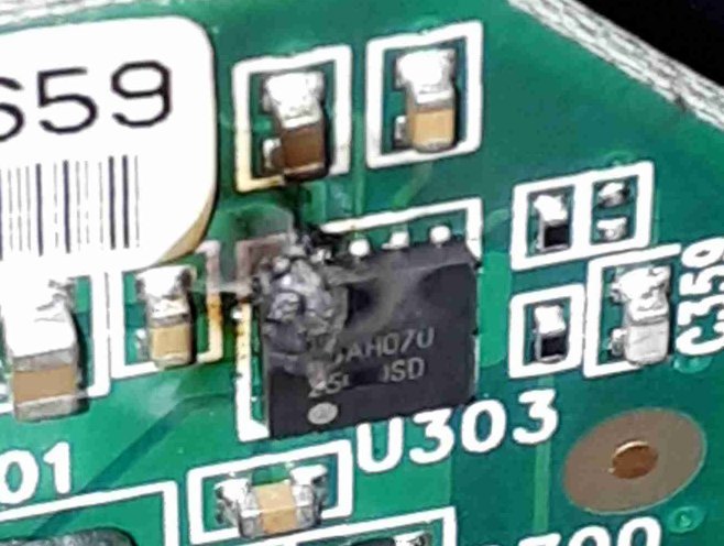
our customer has reported following issue: after several weeks of operation, the LM25010 burns out (please, see attached picture).

Nominal power supply: 24V

We don't know the supplied current (we are gathering this data).

The LM25010 is used to generate +12V and -12V (please, see attached schematic)

are there any macroscopic errors before I start to simulate the circuit?

The customer suspecs possible input surge/burst over 50V

Thank you in advance for your help.

Regards

Riccardo

  • Hello,

    Thank you for sharing the schematic and board image. It looks as though the IC is damaged on the input voltage pin side.  Would you be able to answer my additional clarifying questions for me?

    Which capacitors are the input voltage?  Is the LM25010 directly tied to the 24V power supply?  Is there any additional filtering components or protection components? Also what is the power supply being used? 

    Thank you for your help.

    Best Regards,

    Katelyn

  • Hello Katelyn,

    All capacitors can stand up to 50V.

    There is an input protection circuit (please, see attached picture).

    24V is generated by an expernal power supply not designed by the customer. We have to consider 24V nominal.

    Current required on +12V: no more than 100mA

    Current required on -12V: no more than 50mA

    Bursts and Surges are limited by D2

    Thank you for your help.

    Regards

    Riccardo

  • Hello,

    Can you share your layout as well?

    What is the inductance of L3 and L4? It is possible to have ringing from the large inductances and parasitic loop of the input of the DC-DC. This rining is created after the TVS (at the input of the DC-DC) and not at the power supply. This would lead to a possibility of your TVS to not see it. Do you have a waveform of VIN, SW and VOUT of the LM25010?

    Thank you,
    Katelyn
  • Good morning,

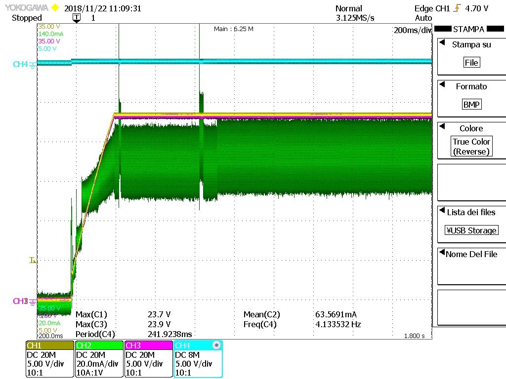
    LM25010 replaced with a new one and hereafter the signals:

    Yellow: Vin (+24V)

    Green: Input Current

    Purple: Vout +24V (should be +12V)

    Light blue: Vout 0V (should be -12V)

    We are completing the check of the board

    Thank you

    Riccardo

  • Good morning,

    we have tested other samples bringing the power supply over the limit because the customer suspecs there are input slow transients over 50V.

    The input protection (TVS Vbreakdown = 36V) cuts fast transients but can stands up to 50V with slow transients.

    The LM25010 easily supports the overvoltage.

    The diode between ISEN and SW pins (Vreverse = 40V) is damaged by the input overvoltage and becomes a short-circuit. Subsequently, the LM25010 burns.

    We need to reduce the TVS Vbreakdown and increase the diode Vreverse.

    Let me know what you think.

    Regards

    Riccardo

  • Hi Riccardo,

    I want to make sure that I am understanding you correctly. I think that I agree with your analysis.

    I understand that the first component damaged is the diode between ISEN and SW pins. What is the input voltage during this time?

    Best Regards,
    Katelyn
  • Hi Riccardo,

    I wan to follow up with you. Would you be able to confirm what is the input voltage?

    Thank you,
    Katelyn
  • Good morning Katelyn,

    The oscilloscope screenshot published a few days ago was taken by measuring a board in which the LM25010 did not look damaged.

    Testing a brand new board with a power supply of 24V the outputs are correct.

    We cannot confirm the input voltage on field.

    Neither our costomer nor the final user measured the input voltage.

    We can only assume that there are strong variations of the power supply.


    Next step, in agreement with the customer, is to bring the power supply over 50V and to show that the diode between ISEN and SW pins burns and consequently also LM25010 burns.

    Best Regards

    Riccardo

  • Hi Riccardo,

    This makes sense. If the power supply is brought above 50V, the LM25010 will be at risk for burning since this is greater than the absolute maximum of the device.

    Best Regards,
    Katelyn