This thread has been locked.

If you have a related question, please click the "Ask a related question" button in the top right corner. The newly created question will be automatically linked to this question.

BQ76920: BQ7692006PWR pin connection

Part Number: BQ76920
Other Parts Discussed in Thread: BQ34Z100, BQ34110

Hello,

I am using BQ7692006PWR IC in our project .The pins of the fuel gauge ic ,VC0 to VC5 are used for the cell monitoring.i want to ask you that if i dont want to monitor the cell then what should i do with the pin?? i.e  VC0 to VC5.pin.

Waiting for your response..!!!

  • Hi Tirthal,
    Please see the connections in the bq76920 data sheet table 8-1. Basically the unused input is shorted to the next input, but the part requires the top cell to be used. So
    for 5 cells use all inputs.
    for 4 cells short VC4 and VC3 and use as the input between cells 3 & 4
    for 3 cells short VC4, VC3 and VC2 and use as the input between cells 2 & 3
  • Hello,

    We are using a battery pack and that battery pack have only 2 wires +Ve and -Ve. The battery pack voltage will be 11.1 v (3.7 V *3 cells).

    As per the details given by the datasheet the IC requires VC 5 - VC 4 INPUT for cell 3 ,VC 2 - VC 1 for cell 2 and VC 1- VC 0 for cell 1.

    But as per the battery pack construction we only have 2 wires +Ve and -Ve.

    So what should be the configurations of the pins.

    The battery specification are li-ion 5000 mAH and 11.1 V (3 cell construction),with 1C discharge rate.

    And accordingly to this can you provide details what should be the Rsns resistor value...?

    My Load consumes 3.5A of current.

  • Hi Tirthal,
    The bq76920 is intended for monitoring individual cells typically inside the battery case. It is really not useful for a pack level only implementation since it must have individual cell voltages to operate. You could simulate individual cell voltages with a resistor divider to make the bq76920 operate and it could respond to the average cell voltage for over or undervoltage. However the bq76920 would not correctly know the individual cell voltages and the resistor divider to do this would be a constant load on the battery which the part would not have a way to disconnect at low voltage.
    Your divider could be large value resistors to reduce the current, and the MCU could switch off the resistor divider at sufficiently low voltage to remove the drain. When connected the MCU could get a battery voltage from the BAT register, but you may want to have the MCU measure directly.
  • Thank you for your reply also can you suggest me some other fuel gauge for the battery pack of 11.1 V and also suggest me the charging ic which has input voltage range of 24 v max and charging current of 2 A.

    Also suggest me any other ic for 3 cell battery pack which have both battery charging and fuel gauge combined if possible.
  • Hi Tirthal,
    The bq34110 or bq34z100-R1 are gauges which will work at pack level. The bq34z100 will require chemistry matching.
    We do not have pack level gauges with chargers.
    Charge ICs are handled by a different group, please post separately so the post will be recognized by someone knowledgeable with those products.
  • Hello,sir

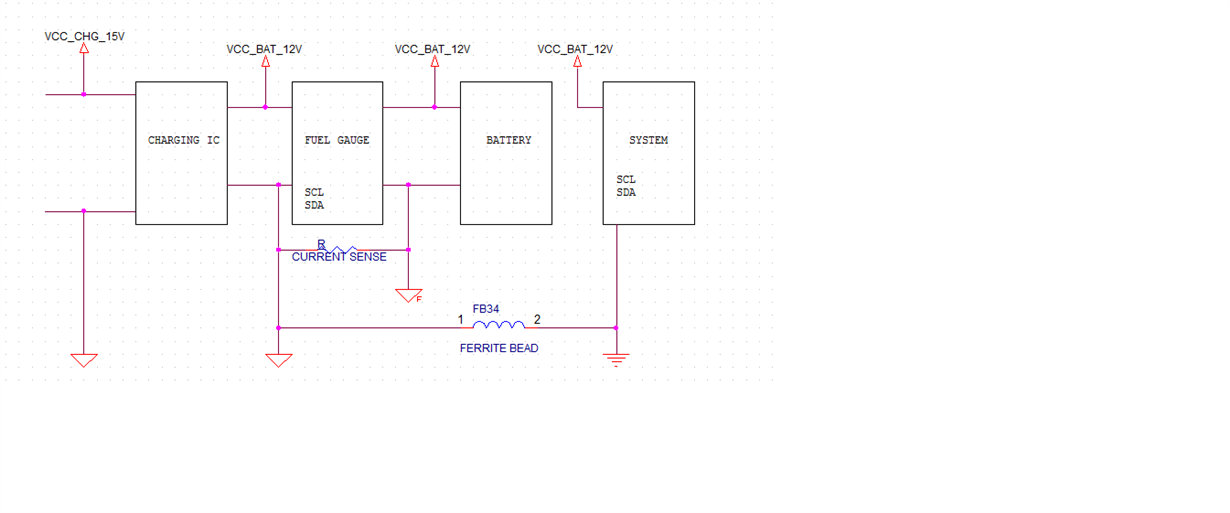
    I have updated the battery construction ,in our battery pack we are already providing the PCM for the battery protection so in our schematic we have bypassed the two mosfet Q10 and Q11 and its other components,and sensed the current through the R195 Resistor,so is this configuration OK....???

    I have also updated the pin connection for the vc-5 to vc-0 pin with the battery.

    I am attaching the schematic document.

    Waiting for your reply...!!!

  • Hi Tirthal,
    The bq76920 VSS should/must be referenced to the cells GND_BAT to keep the voltages in an approprate range. The R200 short across the FETs provides a suitable reference, but does not provide function of the FETs. With a GND on the load side of the sense resistor be sure the sense pins and inputs stay within a safe voltage range.
    The load side of the system would normally go from VCC_BAT_12V to GND at the right side of the FETs so that load current would flow through the sense resistor and FETs when enabled See the concept in figure 8-1 of the data sheet.
    The single ended capacitors can cause negative voltage during cell connection, differential connection of the upper VCn inputs such as in figure 8-1 of the data sheet avoids this.
    REGSRC needs a supply to VCC_BAT_12V, typically with a filter resistor.
    REGOUT needs a filter capacitor, 4.7 uF or 1 uF if not using the supply.
    TS1 needs a pull down and way to boot the part with a positive going edge.
  • Hello,

    Thank you for the reply...!!

    Our system flow is described in the image.

    In our design we don't use the regulator of the fuel gauge ,so is it necessary to connect the REGSRC pin to VCC_BAT_12V...?

    Also we bypass the REGOUT pin by connecting it to ground with capacitor. so is it OK...?

    We dont want to use the thermistor TS1 pin so what should be the status of the TS1 pin....?

    Waiting for your response...!!

  • Hi Tirthal,
    Capacitors for the signals to the bq76920 should connect to VSS. The reference with VSS is normally connected to battery ground to keep all signals in safe operating ranges (within abs max), some designs will connect VSS after the sense resistor where currents are moderate.
    It is preferred to have the bottom of C209 connect to the VSS ground rather than VC0, see figure 8-1 of the data sheet.
    If the battery protection FETs are populated be sure to provide some protection of SCL, SDA and any other signals which may cross the ground reference opened by the FETs.
    Yes, REGSRC is needed even if the design does not use REGOUT externally. REGOUT is used for internal circuits.
    Yes, REGOUT must have a bypass capacitor. Since you are not using it externally a 1 uF is suitable.
    Please note that the bq76920 is a monitor device, with the MCU in the "System" it can be part of a fuel gauge.
  • Hello,Sir

    Thank you for your inputs we appreciate that.!

    As per the updates required we have changed the ground for the Vss pin and connected to the BAT_GND.

    Connected the pin REGOUT with CAP1 pin having value 1 uf cap.

    Connected the REGSRC with BAT pin with filter resistor .

    For the TS1 pin we connected the voltage divider circuit with values 4.7k and 10k .In datasheet it specified that it should have logic above 1v to Keep the IC in normal mode.

    Can you please explain this sentence "If the battery protection FETs are populated be sure to provide some protection of SCL, SDA and any other signals which may cross the ground reference opened by the FETs."..?

    I am attaching you the updated schematic.

    Waiting for your response..!!

  • Hi Tirthal,
    REGOUT and CAP1 are different supply outputs and must be separate with separate capacitors, they must not be connected together. All the caps for the power inputs/outputs should go to the VSS potential.
    C209 bottom should go to the VSS potential.
    C211 and C213 shoud go to the VSS potential.
    A voltage divider is not suitable for TS1, a high level does not keep the part awake, a rising edge is required to wake the part. If you have an MCU which is always awake the MCU could drive the voltage divider when needed to wake the part. See the boot switch alternative apnote in the product folder if you need ideas.
    Regarding the protection switching: When a switch opens the load side of system will collapse to the other system voltage potential. Any interface lines will also pull to that potential. So if you populate/connect Q10 and Q11, and there is a protection event without the adapter powered, the system ground will go to 12V. SCL and SDA will also go to 12V which would be bad for the bq76920 and possibly the MCU. One solution might be to switch the interface also, see www.ti.com/.../slua726a.pdf figure 10. High side switching or isolaiton of the communication path are other options.
  • Hello,sir 

    Thanks for your inputs.

    I have attached the document with the updated file.

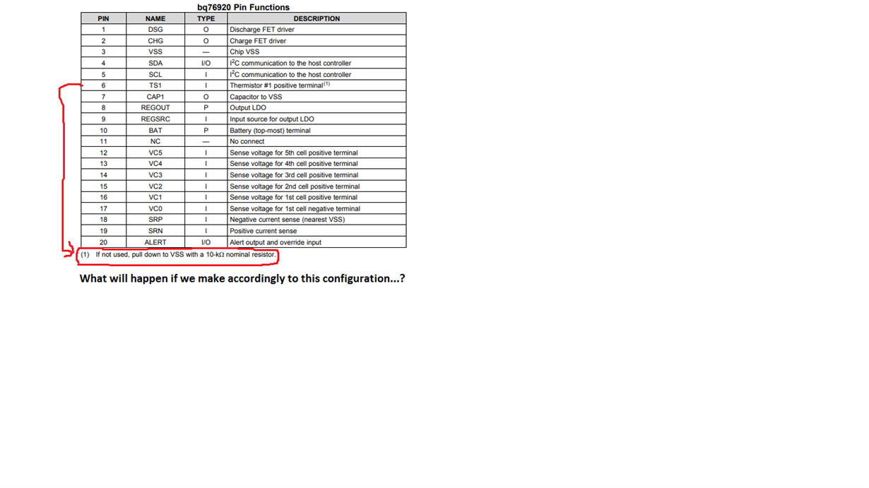
    Also i am attaching you the image file for the pin configuration of the TS1 pin.Why it is grounded to Vss potential with 10k resistor...?

    Also we changed the configuration for the TS1 pin and connected to the MCU pin to wake up the Fuel Gauge is this configuration correct.

    Also can you tell me the event ,when my Fuel gauge will wake up to normal mode or is there any other method in which i can keep my fuel gauge always ON for the normal mode when power up in our application battery will always plugged in...?

    If we bypass the two mosfet Q10 and Q11 will it affect functionality of the fuel gauge for the current sensing....?

    Waiting for your response...!!!!

  • Hi Tirthal,
    The TS1 pin has 2 uses, first to wake the part from a rising edge, second to measure temperature from a thermistor. To get the rising edge the pin must be low. For measuring temperature a 10k thermistor is recommended. So the common suggestion for a pull down resistor is 10k ohm.
    If the pin is left open and floats high, and the part is shut down, applying a high signal will not provide the edge and the part will not wake up. While 10k is recommended in the location noted, other resistor values will work, recall a thermistor changes resistance with temperature. If a thermistor is not used for measuring temperature, any value in the reasonable range is suitable.
    The bq76920 monitor is on after boot, it does not automatically shut down unless the battery voltage drops to the shutdown level. The MCU should apply a boot signal if the part goes to sleep (ship mode) from some unexpected event.
    Bypassing the MOSFETs will not affect current sensing.