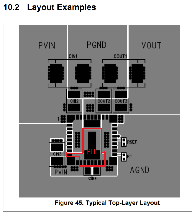
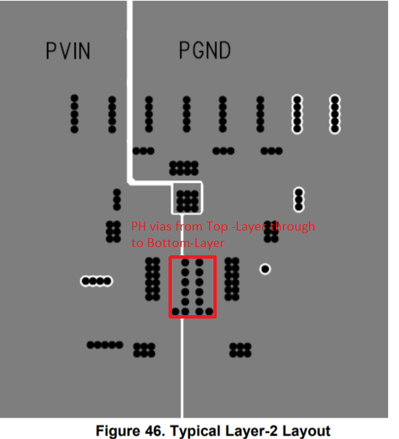
I'm not sure what to do with the PH pins. The datasheet says "These pins must be connected to one another using a small copper island under the device for thermal relief." It looks like the sample layout only has vias surrounding the PH of pin 42. The other PH pins (10, 13-19) don't appear to be connected to the island of pin 42. Further, where are all the vias connected? They are just through the board with no connection to anything? I don't know how this provides thermal relief. Thanks.

-
Ask a related question
What is a related question?A related question is a question created from another question. When the related question is created, it will be automatically linked to the original question.