This thread has been locked.

If you have a related question, please click the "Ask a related question" button in the top right corner. The newly created question will be automatically linked to this question.

UCC27212A-Q1: Comparison with UCC27714

Part Number: UCC27212A-Q1
Other Parts Discussed in Thread: TMS320F28035, , UCC27714, TIDA-00364, UCC27211, CSD19536, UCC27211A-Q1

Dear TI Experts:

I am sorry to bother you.

I hope to design a PMSM driver with Vbus=86V and 3KW for Electric Motorcycle application.  I will use TMS320F28035 as the MCU.

I have spent much time choosing the Gate Driver (for driving the N MOSFET). Could you make the final confirmation for us?

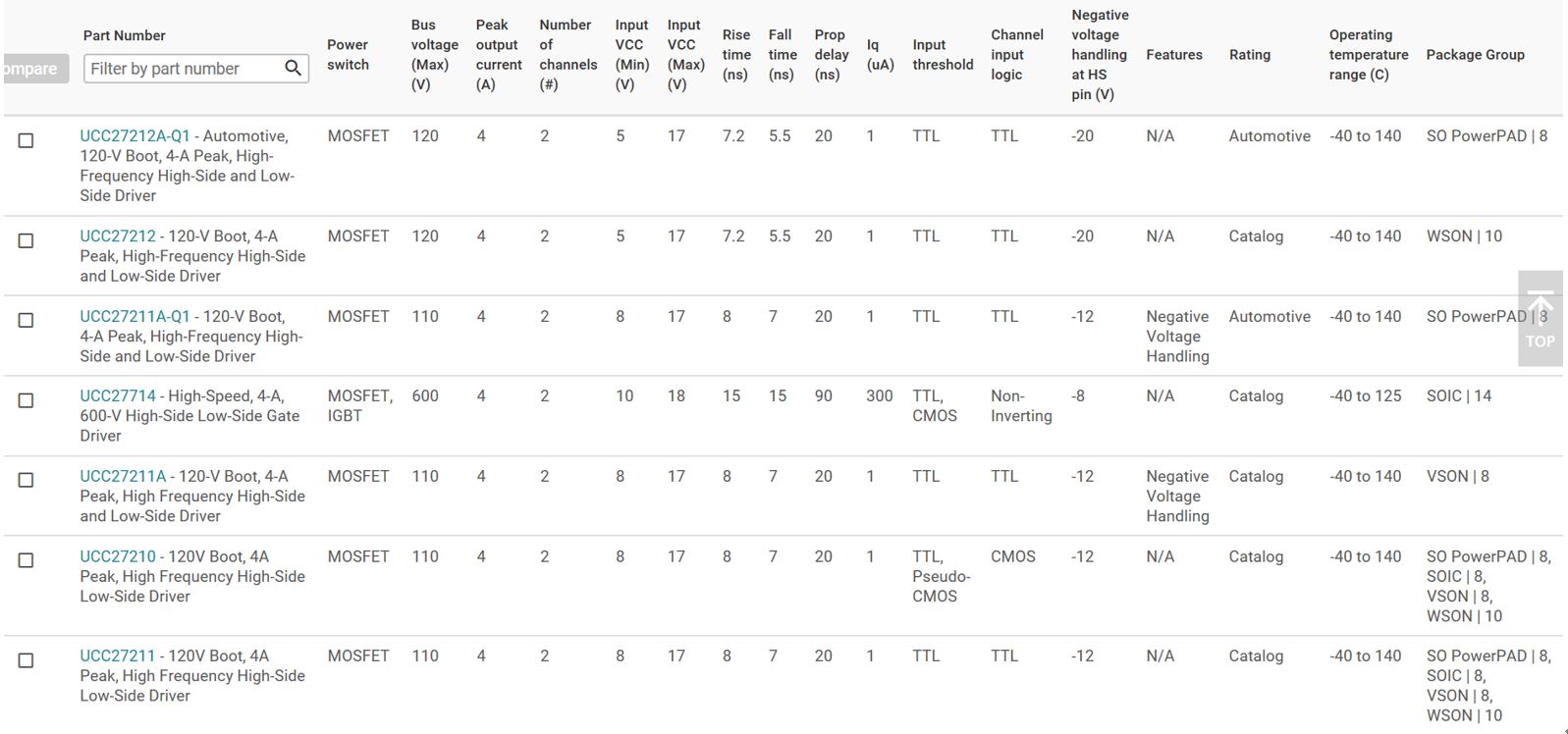
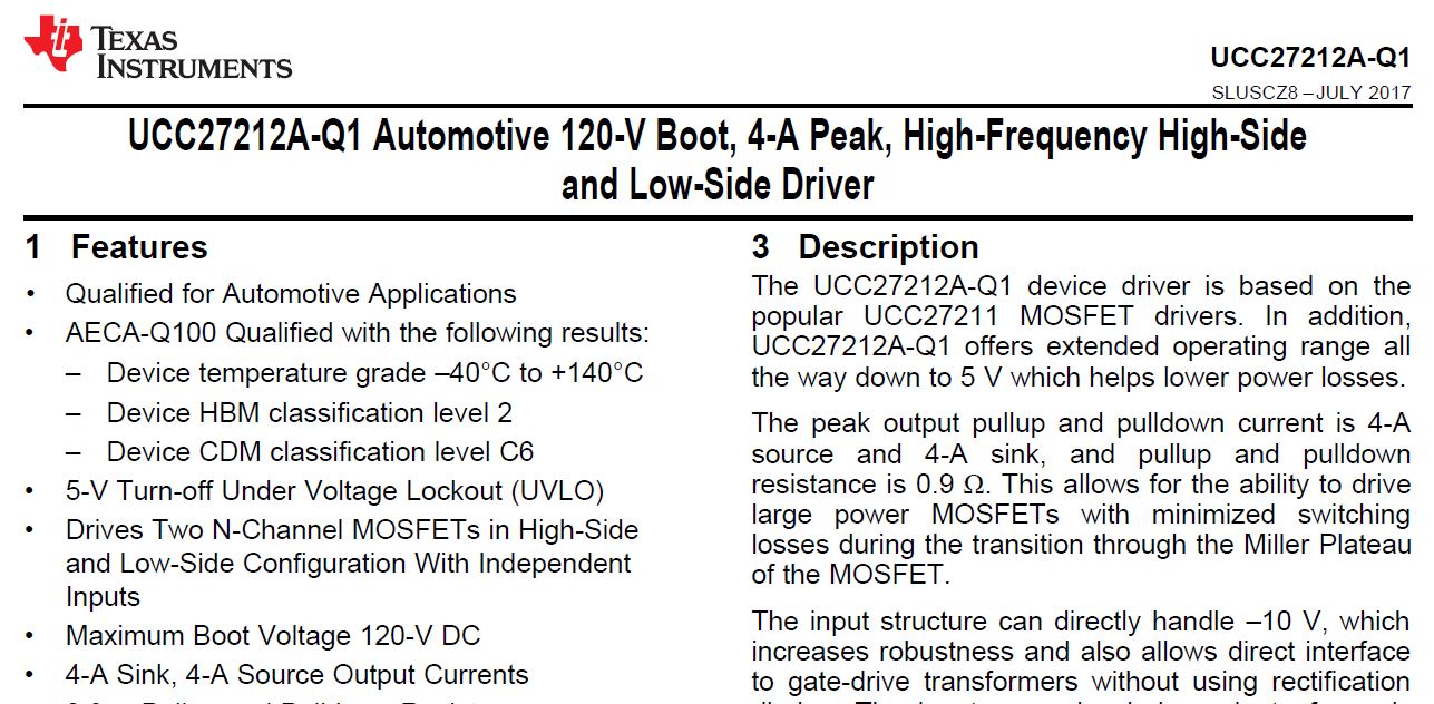
Originally I find that UCC27714 is a good Gate Driver. Recently I think the AEC qualification is important, so I find UCC27212A-Q1.

1. Since Vbus=86V in my design, so UCC27212A-Q1 with bus voltage (Max)=120 is enough for me, right?

Moreover, I find Iq (uA)=1 for UCC27212A-Q1 and Iq (uA)=300  for UCC27212A-Q1. Does it mean that UCC27212A-Q1 can save more power consumption?

Is UCC27212A-Q1 a good choice for my design?   ^_^

2. Finally, does TI provide the related design circuit example for the customer?   ^_^

Look forward to hearing from you soon.

Best Regards,

Tanghan

  • Hello Tanghan,

    Welcome to e2e! I am an applications engineer with high power drivers and will help answer your questions.

    yes, UCC27212A-Q1 is sufficiently rated to handle an 86-V bus voltage. I am assuming that you will be using this in a half-bridge configuration. If so, the voltage on the HS pin is rated for a maximum of 100-V DC (115-V max for repetitive pulse < 100-ns)

    The quiescent current for the UCC27212A-Q1 is the sum of the I_DD, I_HB, and I_HBS quiescent currents which is typically 150uA .
    If this quiescent current is suitable for your application then I would say the UCC27212A-Q1 is a good choice.

    2. Yes, we have a TI design that incorporates the UCC27212A-Q1 on the Tools & software tab of the product folder:
    www.ti.com/.../TIDA-01407 (Automotive 400-W, 48-V battery input, 12-V output power reference design)

    If this post answered your question, please press the green resolved button

    Regards,
    Mateo
  • Dear Mateo:

    Thanks for your professional and instant reply. No wonder TI can sell products so well!   ^_^  May I ask some more?

    1.  In the last mail, I mentioned the Iq due to the following table. Does it mean that UCC27212A-Q1 save more power than UCC27714? 

    2.  I found the design example TIDA-00364 (www.ti.com/.../TIDA-00364, which seems similar to my design. I will substitute the UCC27211 in that design with UCC27212A-Q1. Is it OK? The wire connection seems the same.  Moreover, it is 48V 5KW in TIDA-00364, but it is 86V 3KW for my design. Do you think there is something I should pay special attention to? 

    Look forward to hearing from you soon!

    I appreciate your help so much!

    Sincerely,

    ^_^

    Tanghan

  • Hello Tanghan, 

    1) During stand-by, the UCC27212A-Q1 will consume less power than the UCC27714.

    2)Yes, it will be okay but take note that UCC27212A-Q1 has less source and sink current capability (1.3 A/1.7 A) than the UCC27211 (3.7 A/4.5 A). This will slow down your switching times. The gate resistors on the schematic will have to be adjusted. Please look through our external gate resistor selection guide here:


    For the different bus voltages, I would make sure that your MOSFETs are selected to handle the BUS voltage + additional margin in case of ringing. 

    I hope this answered your question. If so, please press the green resolved button. 

    regards,
    Mateo

  • Dear Mateo:

    Thanks for your reply and sharing your valuable article with me.

    I am sorry that I still have some questions.

    1. You mentioned that "UCC27212A-Q1 has less source and sink current capability (1.3 A/1.7 A) than the UCC27211 (3.7 A/4.5 A)".  But I find "4-A Sink, 4-A Source Output Currents" both in the UCC27212A-Q1's and UCC27211's datasheets.

    If UCC27212A-Q1 has the same specification as UCC27211, then I can directly substitute UCC27211 with UCC27212A-Q1 in TIDA-00364 design, right? (Thanks for reminding me that "make sure that your MOSFETs are selected to handle the BUS voltage + additional margin in case of ringing." )

    In TIDA00364's design,  there is a circuit, composed of  MJD45H11RLG, between UCC27211D and MOSFET (CSD19536). It will be easy for me if I can directly substitute UCC27211 with UCC27212A-Q1 in that design.   ^_^

    2. I will use Altium Design to draw the circuit. Could you show me where I can download the UCC27212A-Q1 component for SCH and PCB?   I really need your help. I appreciate your help so much!

    ^_^

    Best Wishes,

    Tanghan


  • Hello Tanghan,

    The UCC27211A-Q1 has different source/sink specs depending on Vdd (6.8V or 12V) . Looking through the TIDA-00364, it looks like they are using VDD = 12V, which will give you 3.7A/4.5A.

    Yes, you can directly, substitute the UCC27212A-Q1 into the design.
    The pnp BJTs help to quickly turn-off the MOSFETs. This is to prevent a shoot-through condition.

    Currently, we do not have the components for the UCC27212A-Q1 but the UCC27211 has its files located here: www.ti.com/.../pinout-quality

    They are the same pinout and package (DDA). To the right of the CAD/CAE section of the above link there are instructions on how to view the CAD symbols.

    If this answered your question, please press the green resolved button.

    regards,
    Mateo
  • Dear Mateo:

    Thanks for your instant reply and kind help.

    I can't help but consult you one more question. ^_^ Every time I hear from you, I always learn a lot!!! ( But I think I should have pressed the green resolved button. ^_^)

    For FOC control of PMSM, it seems TI provides many design examples for sensorless FOC control, but few design examples for sensored (for example, encoder as the sensor ) FOC control.

    If you know some design examples on the sensored (for example, encoder as the sensor ) FOC control (with TMS320F28035 or other MCUs), could you kindly show me?

    ^_^

    Best Regards,

    Tanghan
  • Hello Tanghan,

    No problem. We are here to help!

    Check out this TI design: www.ti.com/.../tidu967.pdf
    It is a 3-phase BLDC and PMSM motor drive that includes a 6000-rpm, 7.1-A teknic motor with a built-in quadrature encoder!

    I believe we're starting to stray away from the original topic. Please post a new thread if you have a new question. Thank you!

    If this answered your question, please press the green resolved button.

    regards,
    Mateo
  • Dear Mateo:

    Thanks for you professional and valuable comments and suggestions. ^_^

    You are so kind to me~ Many thanks~

    Wish you the best


    Tanghan