Other Parts Discussed in Thread: TPS62740, TPS22941, TPS22924, TPS2595
Hi,
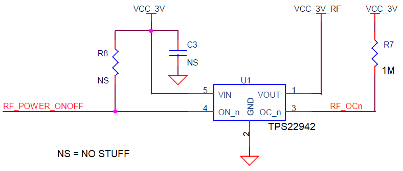
I am pursuing TPS22942 and made a circuitry (shown below) for powering on/off the supply source to a RF module. RF module takes 45mA approx. VCC_3V is the input source and VCC_3V_RF is the output. While I am making RF_POWER_ONOFF='0', VCC_3V_RF is going to 3V. However it is going to 2.3V approx while RF_POWER_ONOFF='1'. Below is the waveform. I am fine with the RF_OCn behavior as shown in below waveform. Also I have measured that VIN voltage is steadily 3V at all times (no spikes/dips).
I checked the behavior of RF module with another circuitry that has a switch. Basically I used a voltage regulator TPS62740, and controlled its CTRL pin for powering on/off the supply source to RF module. The LOAD output from this regulator is properly powering on to 3V and powering off to 0V. So, there does not seem to be any issue with the RF module.
I have also checked the above TPS22942 circuitry behavior without any RF module connection. Then, the switch seems to behave as intended. VOUT is going to 0V when it is switched off.
I don't think the above abnormal behavior of TPS22942 is due to output/input capacitance values, because the output remains at 2.3V continuously. Not sure if I am missing something in its behavior. Kindly suggest why TPS22942 is behaving as above, and how can its VOUT behave appropriately. Kindly let me know if you need any further info from my side.
Thanks & Regards,
Vikas Chandra Rao.


