This thread has been locked.

If you have a related question, please click the "Ask a related question" button in the top right corner. The newly created question will be automatically linked to this question.

UC2903: Issue with "Power OK" output

Part Number: UC2903

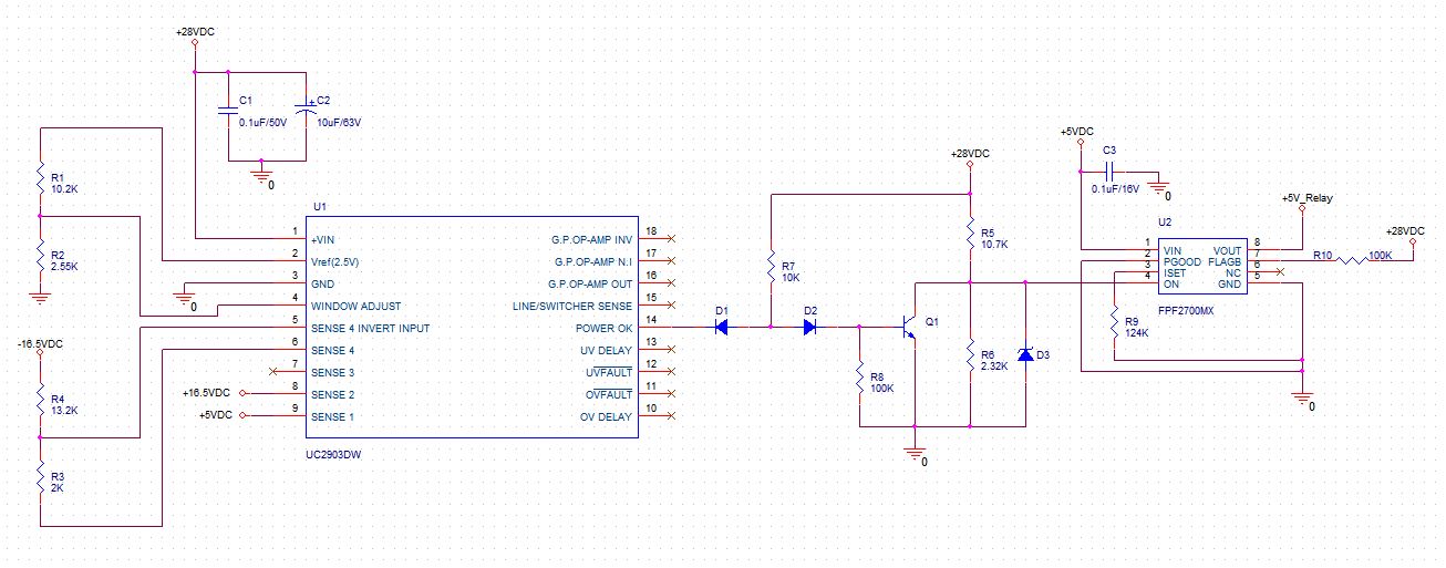
I need to use the "Power OK" output of UC2903 to activate a load switch (The load switch requires an active low signal on the "ON" pin to enable VOUT. The VOUT needs to be disabled when the monitored power supplies fall out of tolerance). I'm monitoring three DC power supplies viz. +5V, +16.5V & -16.5V and my Input Supply is +28VDC. The fault window has been set for a tolerance of +/-5%. I'm not getting the desired "Power OK" output to activate the load switch (the "Power OK" output is always LOW).

Please review my implementation of the power monitoring IC and suggest any improvement, if required.


- Vijay

  • Hi Vijay,

    Can you test the functionality of the "power ok" without the diodes but with a pull up to see if it works?
    I want to make sure the device is functional then we can work on the secondary side

    -Marcoo
  • Hi Marcoo,

    Thanks for the tip.

    I have de-mounted D1, D2 & R5 and I have put a jumper at the place of D1 (pulling-up the "Power OK" output to 28VDC through 10k resistor).

    But, I'm not getting the desired voltage at the "Power OK" output.

    - Vijay

  • Hi Vijay,

    I believe the "POWER OK" output is also tied to the "LINE/SWITCHER SENSE" input as well. The LINE/SWITCHER SENSE is internally referenced to 2V so when this input is less than 2V, POWER OK will be active low to show a fault. When LINE/SWITCHER SENSE is above 2V, POWER OK will be logic high to show no fault.

    Please confirm this is the issue you are seeing. Thanks!

    -Michael
  • Hi Michael

    Please find the schematic

    - CWD pin connected with 0.1uf, and it is giving pulses

    - WDI pin also giving pulse (Controller)

    -  When we switch on the device WDO and RESET pin in High state, when we stop the pulses this pin and going to low .

        That means it is not giving reset to controller

    - My be TPS3852 is not starting

    - Please provide sequence of enable and working procedure

    -Jay

  • Jay,

    I can not see the schematic that includes TPS3852. Please send schematic to my email at michaeldesando@ti.com so we can get this figured out. Thanks!

    -Michael