Hello Community,
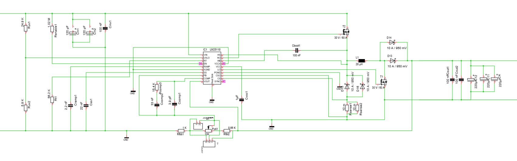
i have a Project with the LM25118. The circuit i use is that one of the data sheet. My only change is a potentiometer on the FB pin to regulate 24V and 12V.
My Problem is the Output of this Board. When I connect a lower Load my Output fall down to a lower Voltage then i prefer.
My first consideration was that the inductor creates a magnetic field and so the Rsense throws the board into the current Limit.
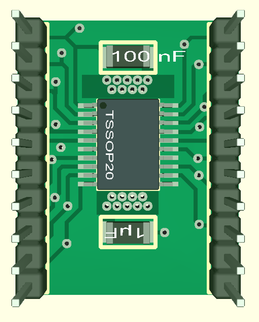
So that this can be ruled out, I brought the Rsense as close as possible to the chip and led the lines parallel.
But if i take a lower load this means a higher current my Output falls down.
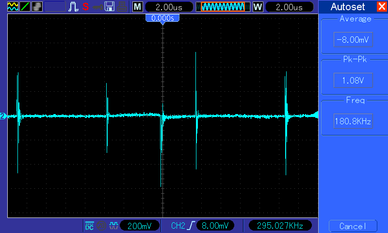
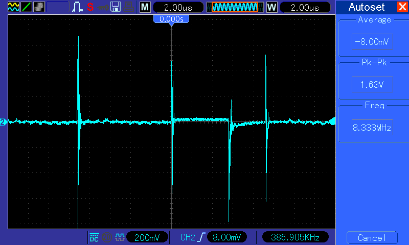
I take a graph of the Rsense so i can see very big Voltagepeaks at the Point.
At the same time i take Picture of the CS and the CSG Points.
That ist the Graph of the CSG-Pin. This Graoh was although at the CS Pin.
At this point I have separated the ground tracks. This has helped to prevent the voltage drop in most cases. Nevertheless, I lose the voltage at a load of 3.3 ohms in boost mode. In Buck mode I have no problems.


This is with seperate the Ground tricks.