This thread has been locked.

If you have a related question, please click the "Ask a related question" button in the top right corner. The newly created question will be automatically linked to this question.

LM5085: Help me check the layout of LM5085

Part Number: LM5085
Other Parts Discussed in Thread: LM5145, LM5185

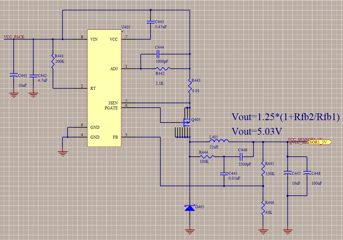
I have made a DC/DC with LM5085, but the voltage will drop when the load is added.

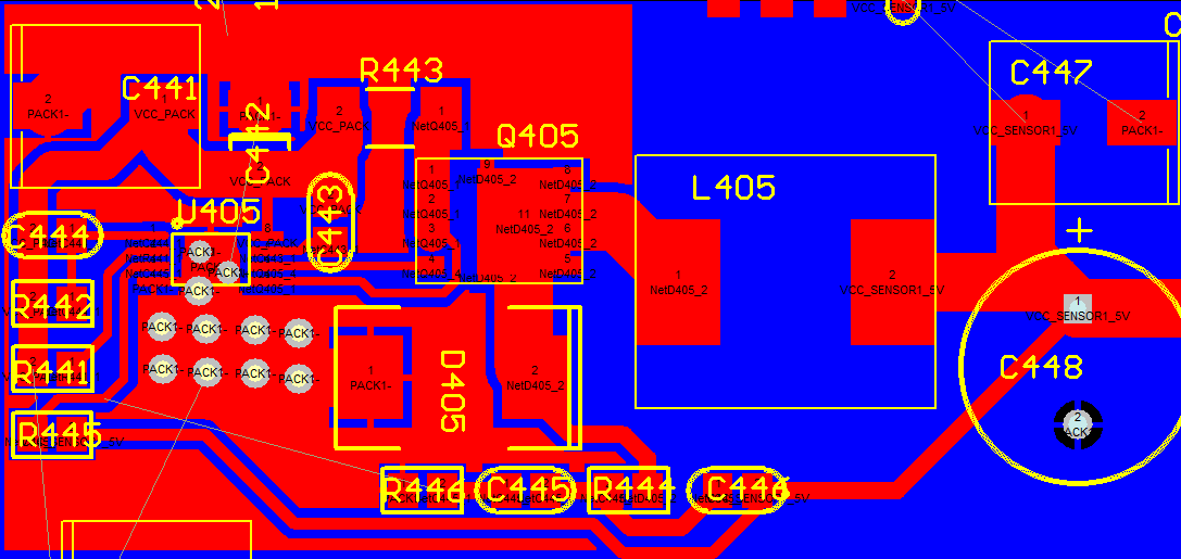
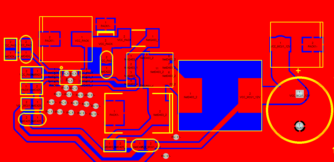
Therefore, I have changed the layout of LM5085.

The schematic and PCB is listed as below.

Would you help me have a check?

Would it be OK  for 7A load?


  • Hi Wu,

    Please complete the LM5085 quickstart calculator (available by download from the product folder) so we can review the component values. You may want to consider a synchronous controller for a 7A output as the freewheeling power diode loss will be quite high for a non-synchronous solution. Depending on the required input voltage, the LM5145 may be an alternative.

    In terms of layout, it's important to closely locate the high-side FET (Q405), freewheeling diode (D405) and input ceramic capacitor (C442) in a tight loop as this loop has very high di/dt. Locate a full GND plane on layer 2 of the PCB and use vias to connect to the return terminals of the input caps.

    Lower FB resistor (R446) should be close to the FB pin. The FB trace should be as short as possible.

    Regards,
    Tim
  • The input voltage is 42V~51V and the output is 5V
  • Hi Wu,

    Please review the LM5145 synchronous buck controller. Given the 7A output current, this will provide higher efficiency than a non-synchronous solution.

    Regards,
    Tim
  • How about this one?

    Is it perfect for LM5085?

  • Hi Wu,

    Here are some recommendations:

    1. Stack R446 above C445 so that the trace back to the FB coupling cap is kept away from SW.
    2. Connect diode directly to inductor (not to the FET).
    3. Maintaining low impedance between the return connection of the input cap and anode of the diode is critical (key loop is MOSFET-diode-input cap). Add GND vias near input ceramic cap to improve that connection.
    4. Use full GND plane on layer 2
    5. Use less thermal relief and increase the copper connecting the diode and input cap pads.

    What is the ESR of the output electrolytic? Maybe consider using a ceramic in parallel.

    Finally, have you considered diode power loss at 7A (2-3W, depending on VIN)? This is why I recommend considering a synchronous solution with low-side FET instead of a diode.

    Regards,
    Tim
  • Thanks a lot.
    We do not use LM5185 because we have bought LM5085.
    Thank you for your suggestions.