This thread has been locked.

If you have a related question, please click the "Ask a related question" button in the top right corner. The newly created question will be automatically linked to this question.

Compiler/TPS630250: Regulator is heating

Part Number: TPS630250

Tool/software: TI C/C++ Compiler

Hello,

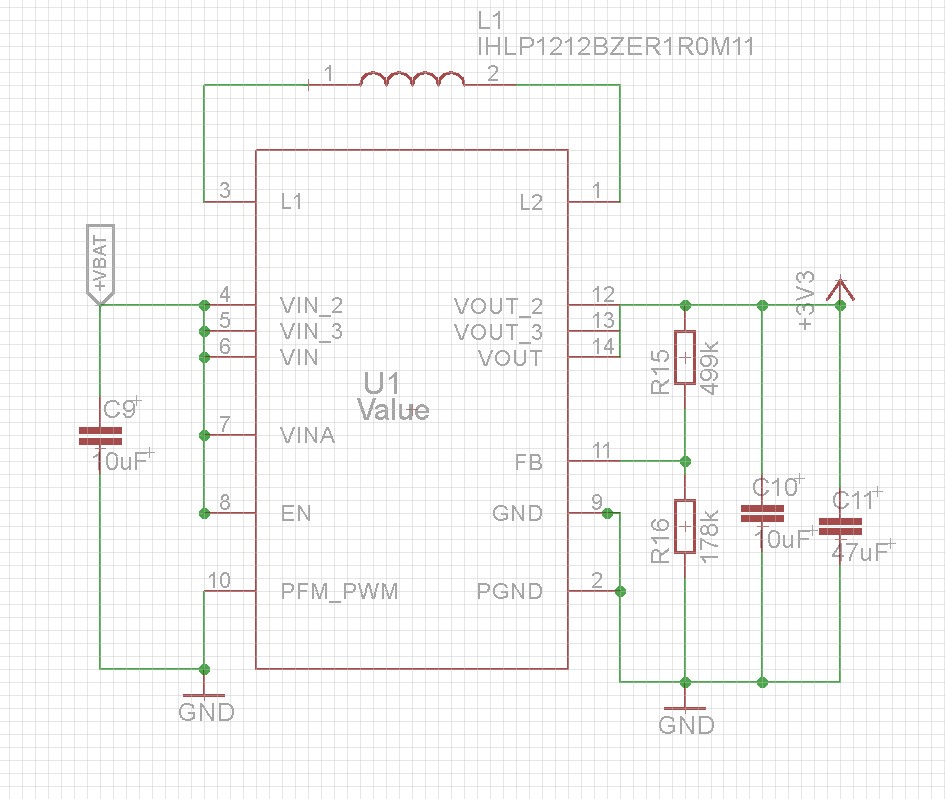
I have a custom pcb with TPS630250 and resistor are regulated to 3.0V ( R2=178k R1=500k)

Sem-T-tulo

Sem-T-tulo1

The input voltage is 3.7V if power is battery, or 5V power is USB. The output is 3V and circuit its working well but the heat is a problem because all PCB is heating.

Someone had this problem?

BR

  • Hi Roberto,

    Could you please answer the following questions:
    1. What is connected as the load and what is the output load current?
    2. Is the board heating with or without the load?
    3. Can you measure the temperature of the device and the inductor?

    Best regards,
    Milos
  • Hi Milos,
    I have tested in two PCBs and the problem is the same.

    1. What is connected as the load and what is the output load current?
    The load is amps, ICs , BLE module and some resistors, the currente is less of 100mA ( i measured).
    2. Is the board heating with or without the load?
    Without load, the board heating a little (i can stay with a finger), with load the board stays very hot.
    3. Can you measure the temperature of the device and the inductor?
    i cant measure yet, but i cant stay the finger on inductor.

    Do you have this problem?

    thanks.
  • Hi Roberto,

    Under those conditions (Vin=3.7 - 5 V, Vout=3 V, Iout=100 mA) the components on the EVM are not heating considerably. That should also be the case with a design that follows the recommendations from the datasheet.
    1. Could you please check the schematic and the PCB layout (if possible post the images here or send it directly to me), and how much does it differ from the EVM?
    2. What is the exact part number of the inductor?

    Best regards,
    Milos

  • HI Milos,

    Can you check the schematic in image bellow. the reference of inductor is in image.

    Br

  • Hi Roberto,

    The schematic looks fine. Can you also show the PCB layout? Are all those capacitors ceramic type?

    Best regards,
    Milos
  • Hello Roberto,

    As I did not hear back from you, I expect that you solved your problem.

    If this is not the case, please post again to this thread or open a new thread.

    Best regards,
    Brigitte