This thread has been locked.

If you have a related question, please click the "Ask a related question" button in the top right corner. The newly created question will be automatically linked to this question.

LM74610-Q1: LM74610-Q1 and PV arrays help please!

Part Number: LM74610-Q1

Has anyone any experience with using LM74610-Q1 with Photo-Voltaic panels?

I wish to use LM74610-Q1's to 'OR' several 12V PV panels in parallel.

Using even schottky diodes isn't an option due to forward current power losses and associated heat. (the panels are 3Amp and 6Amp devices).

I believe I need to protect each panel from reverse current when maybe one panel is shaded and could be reverse biased creating a 'hot spot' and damaging the shaded panel.

However I am worried that the LM74610-Q1 may not detect  a 'slow' change in reverse current (as would happen as a panel becomes shaded) and also ...if the panels don't all generate exactly the same voltage (even from new) could panels become permanently excluded from the array?

Any expert guidance or anecdotal experiences gratefully accepted.

Thanks in anticipation

Dave

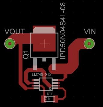
  • OK so I bit the bullet and made a pcb for the LM74610-Q1 comprising the device plus a IPD50N04S4L08A N MOSFET and a 2u2F mlcc charge pump capacitor. (attached)

    I used two variable PSU's both with a 10 Ohm across the output (so they can sink current) with both -VE terminals strapped together and set one to 12V. I fed this 12V supply through the assembled pcb which had a 2R2 connected in series as a drain load. So the circuit was as follows:- From +ve of the psu to the source of the pcb (Vin), the drain (Vout), to a 2R2 and back to the -ve of the psu.

    Monitoring the current I could see the device momentarily pulsing showing the assembly was working as expected.

    I now connected the output of the second psu to the drain of the N Mosfet (Vout) and slowly turned up the voltage monitoring the current in the primary circuit. I could see the current through the Mosfet reducing as the voltage of the second psu approached 12V and when the second voltage exceeded the first, the current stopped at zero. Exactly what I expected the LM74610-Q1 assembly to do.

    However ...... turning the second psu down and back up again this time the current went negative meaning the LM74610-Q1 didn't detect a reverse current condition.
    Similarly, turning up the second psu above 12V and suddenly applying it to the drain (Vout) results in an approximately 50% success rate that the LM74610-Q1 detects the reverse current and disconnects.
    This is hopeless as the whole idea is the device is supposed to be a reverse current protection device.

    So ... assuming that the device is designed to work every time,  I must be doing something wrong in my test regime?
    Why doesn't the LM74610-Q1 detect reverse current conditions every time in my tests, and how do I make it 100% reliable?

    Texas engineers, PLEASE help!!!

    Dave


  • Hello Dave,

    For ORing two power sources with LM74610-Q1, power sources should be connected to source of each MOSFET (ANODE pins of LM74610-Q1) and drain pins should be shorted with each other as shown in Fig 21 on Page 18 of the datasheet.

  • Hi Lokesh
    Yes this is what I am doing in effect. I am using one LM74610-Q1 powered from a variable supply (PSU1) to power the load.
    I am then simulating a second LM74610-Q1 assembly with a second variable PSU connected (ORed) to the Drain of the LM74610-Q1 assembly.
    I am monitoring the current through the 'primary' LM74610-Q1 circuit.
    When I turn up the second PSU the current through the LM74610-Q1 circuit reduces as current from PSU 2 cancels the current from PSU1.
    Increasing it further reduces the primary current to zero. At this point I assumed the LM74610-Q1 will turn off it's associated MOSFET to prevent negative current flowing back into the LM74610-Q1 assembly.
    AND... this does happen at least 50% of the time. But sometimes the current goes negative meaning the MOSFET didn't turn off.
    There are two states for this negative current behaviour.
    1). The current goes negative but switches to zero at the next 'charge capacitor' timeout, (I have a 2u2F cap so the cycle time is quite slow).
    2). The current goes negative and stays negative until I reduce PSU 2.
    As I understand it the LM74610-Q1 should detect current flowing backwards and shut off the MOSFET within 2 microseconds.
    So.....
    Is the LM74610-Q1 not suitable for use with slowly changing reverse current?
    Does it expect a fast edge/change to trigger MOSFET shutdown?
    Why does the LM74610-Q1 work OK many times but fail to detect reverse current at other times?
    Maybe I should be using an LT4359 and P fets?

    I can't afford to produce a system that isn't 100% foolproof....all thoughts welcome.
    Thanks
    Dave
  • Hello Dave,

    For LM74610-Q1; The threshold(VANODE-VCATHODE) for detecting reverse polarity(or reverse current) is -20mV. This is explained in section 7.3.3.1(on Page 9) and Fig 1(on Page 5) of the datasheet.

    As you are using IPD50N04S4L08A MOSFET (with RDS = ~7Ohms) , it would mean that a reverse current of ~3A should flow to turn-off the MOSFET. To verify this, you can monitor voltage across ANODE, CATHODE and Gate Pull Down Pin in case of reverse polarity.

    To turn-off MOSFET at lower values of reverse current, a MOSFET with higher RDSon can be used but this would lead to higher conduction losses in the MOSFET.
  • Hi Lokesh

    Many thanks for your reply, I now realise that really I am using the wrong approach to the whole problem. The LM74610-Q1 seemed a great idea when I discovered it but it has begun to dawn on me that I don't really need a 'floating controller as all the PV negative sides are commoned. I can therefore use a controller that is referenced to ground and therefore don't need one with a charge pump. Guess I was blinded by the technical genius of the 'chip' whereas I can get away with a much simpler system.

    Thanks for all your input and patience, I believe I can now resolve the situation.
    Best wishes
    Dave