This thread has been locked.

If you have a related question, please click the "Ask a related question" button in the top right corner. The newly created question will be automatically linked to this question.

UCC28951-Q1: Gate pulses at the time of start

Part Number: UCC28951-Q1
Other Parts Discussed in Thread: UCC28950, UCC21521

Hello 

I have designed the controller for DC DC converter using UCC28951-Q1. here iam attaching control circuit pdf0724.Control circuit edited new 1.pdf

When i test the control card alone without giving vout feedback and CS pin signal to control card , I found the gate pulses of four ouputs A B C D with square pulse of magnitude 12V (VDD) ,100khz ,50%duty cycle, with some delay which i have set from the delay time resistors..But this should not happen at the time of start because now i will give these pulses to the PSFB mosfets and that will have the output.

1. my question is My operating range of dc dc converter is 310 vdc to 410vdc.

when we enter into operating range,the controller will start pulses to generate and should give some output at the output side. But that is not happening which i mentioned earlier. and it should stop the pulses generating after the operating range. what is the reason and is there any feature like this ?

Thanks and regards

Rajashekar

  • Hello Rajashekar

    What you are seeing is expected behaviour. If there is no input voltage to the power train and VCC is applied to the UCC28951-Q1 controller then the OUTA, OUTB, OUTC and OUTD signals will be present. Each of them will be at 50% duty cycle - less a little to allow for the dead times you have programmed. The controller will operate at Dmax because the output is below its setpoint. There is no input voltage sensing feature on the UCC28950 so it will run the power stage at any input voltage from 0 right on up to the maximum input voltage. This is a useful tool for debugging because you can run the power train at low input voltages (like 20V or 50V) and see if it is running ok before increasing Vin to the normal operating range.

    If you want to stop the UCC28951-Q1 from doing this then you can hold the SS/EN pin low and then release it once Vin is in the range you want.
    A small signal MOSFET from SS/EN to GND with a control signal input to its gate will do this.
    Regards
    Colin
  • hello Colin

    1) but when we increase the voltage from 0 to 50Vdc input side , there is flow of current of 2A @50Vdc .with this when we reach the operating range 310-410Vdc , the current rating of mosfet will exceed and will blast. That had happened for two times and we confirmed by adding resistor in the input side. Now what should be done ?

    2) In the second paragraph you mentioned , that you mean it reqiures external one mosfet to control ss/en pin ? From the same controller , cann't we achieve that it should start giving pulses from operating range? 

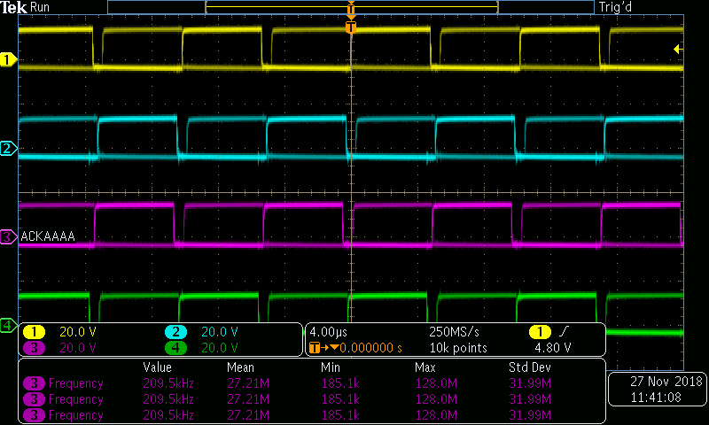
    3) here Iam attaching the pulses at time of start i.e, when i give external 12V supply to controller and there is no CS signal and No Vout to the controller.

    and one more i want to mention that ,Can you see channel A that there are two pulses which are seen one over the other ?and what is the reason for it ?

    Thanks and regards

    rajashekar

  • Hello Rajashekar

    The UCC28950 does not have a UVLO on the Vin of the power stage. If you want an input voltage UVLO then you need some external circuit and use the SS/EN pin to disable the UCC28950 until the input voltage is in the correct range.

    On the 'scope plots - please double check that you are triggering on the same edge each time ? It's not possible to be sure but there seems to be a 'thickening' of the negative going edge which gives the possibility that the 'scope is sometimes triggering on the real positive going edge and sometimes on a positive going spike on the negative going edge. This is the first thing I would check - speed up the timebase to see if this is the case then do a single shot trigger, or trigger on a lower or higher level.

    If there is a current flow of 2A at 50V in that would be 100W in. What is the output power at this time ?
    I would keep Vin at a 'safe' level - (a level where the power train does not blow up - perhaps < 50V) and carefully examine the switching waveforms and the CS signal to make sure that the transformer voltage waveforms are ok before increasing Vin to the final level.

    Regards
    Colin
  • Hello Colin

    Thanks for the reply

    We are using UCC28951-Q1 controller IC. We are testing the power circuit by providing 12V to the controller IC from the external supply.

    We used the UCC21521 isolated gate driver IC after the controller IC and we obtained those gate pulses and given to PSFB mosfets.And we started to increase the input voltage to the Converter from 0V.

    We connected 10ohm load at the output side. We found there is minute increasement in voltage but no current ( at 0A ). We had also found that there is large noise in transformer voltage waveforms and there is change when we increase the voltage.  this is the controller circuit diagram1207.Control circuit edited new 1.pdf

    Power circuit circuit diagrampower circuit updated 20-11-18.pdf

    But what i see is CS signal is not sensing properly and can you rectify it why that is happening so.? I used D1 as 1N4007 normal general application diode.

    Do i have to use any resistor between SS/EN pin and gnd for soft start ?

    Thanks and regards 

    rajashekar

  • Hello Rajashekar

    I'm afraid that the 1N4007 diode will be completely useless to rectify the CS signal because its reverse recovery time is very long - this series of diodes is useful only at line frequencies. I'd suggest you use a 1N4148 instead.

    I see you have not used a 'shim' inductor in the primary of the main transformer - please check your calculations for the inductance needed to drive ZVS and see if the transformer leakage inductance is sufficient. If not then you should include the shim inductor.

    Regards

    Colin