This thread has been locked.

If you have a related question, please click the "Ask a related question" button in the top right corner. The newly created question will be automatically linked to this question.

UCC29002: Instability in load share and compensation component calculation

Part Number: UCC29002

Hello,

My customer is working with the UCC29002 and he is having a couple issues and needs some support:

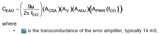
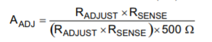
The first problem he has is with the calculation for the RC values using the equations in the datasheet (pg.17 SLUS495I) for their desired loop response.

The R_EAO result being squared is negative. Have you encountered this issue before? what could be the cause for the negative?

the second problem he has is instability in the load share where he is seeing bang-bang behavior in the supply currents.

Are there some key factors that usually lead to such a behavior? how can we stabilize it?

some background:

"The converter it works with is based on a LT3839, which is stepping down 12V to 5V with a max current of 40A @5V.

Bode plots from LT simulation give us a 20kHz bandwidth with 45dB of gain margin, and 30dB of gain at 2kHz."

Thanks,

Kevin


  • Hello Kevin,

    The value of REAO will not be  a negative value if the value of CEAO is calculated properly.

    To calculate the value of CEAO you need to measure the value of the power module at the desired crossover frequency.
    Results based on an LT Spice simulation are very questionable. You should use the measurement procedure detailed in the data sheet.

    Regards

    John

  • Hi John,

    Thanks for your reply, we'll look into performing that test, but I'd still like to see if we can get calculations that work out with the datasheet equations. Could you please clarify the following? (this is mostly about SLUS495I page 17)

    - there are two "gm" variables on that page, one "gM" in the Ceao equation that is referred to as the transconductance gain of the error amp, and another "gm" that's all lowercase and could refer to the gain margin of the system as defined in section 8.2.1. Can you confirm whether the transconductance gain should be used in both instances?

    - equation (11) seems wrong and we've found example calculations where Aadj is calculated as Radj x Rsense / (500 x (Radj + Rsense)). Is the datasheet version correct?

    - if an imaginary value was to be found for Reao, is the recommended approach to dither around the calculated value of Ceao until something works? What other things could we try?

    Regards,

    Sam Underwood

  • see customer response below
  • Hi Sam,

    Is it possible to upload the values that you entered into the equation? that way we might be able to spot any oddities.

    also, from looking at the datasheet whereby Reao is dependent on Ceao:

    gm looks to be the trans-conductance gain of the amplifier.

    Thanks,
    Kevin

  • Hi Kevin,
    On the subject of gM, I was referring to the one in eq 13, which has a different font, similar to the one in section 8.2.1.
    Parameters for our calculations:
    Rshunt = 0.5mohm
    Iout max = 40A
    Vout = 5.2V
    Radj = 22 ohms
    Igain = 200
    fco = 500 Hz (simulated converter bandwidth of 24kHz)
    Apwrfco = 300
    Rsense = 1k
    Thanks,
    Sam
  • Hello  Sam,

    If I may respond to your original question which was addressed to me.

    There is an error in the SLUS495I data sheet.

    Equation 11 in the SLUS495I and the prior revision SLUS495H are different
    T
    he above equation is taken from Rev H data sheet

    And the equation below is taken from Rev I data sheet.

    I am attaching Rev H data sheet for reference.

    Can you please use the equations in Rev H and let me know how you get on ?

    I apologise for this and the data sheet will be corrected.

    Also "g suffix M" and "g non-suffix M" are the same parameter. This also is a datasheet error.

    Thank you for finding this and sorry for the inconvenience.

    Regards

    JohnSLUS495H.pdf

  • Hi John,

    Thanks, that is very helpful.

    We were able to get improved stability by using the updated equations and reducing our Rsense from 1k to 100 ohms. Do you have insight as to why this may be?

    Regards,

    Sam Underwood

  • Hi Sam,
    Glad to hear the new equation worked.
    Rsense is the internal resistance in the power module between+Vout and +Sense.
    It is normally between 50 and 100 Ohms. This sets the adjustment range of the output voltage.
    You normally only want 1% to 2% range here.
    If you make Rsense very large the current through the ADJ path is going to be very low.
    This will make your system very prone to noise pickup.

    Regards
    John