This thread has been locked.

If you have a related question, please click the "Ask a related question" button in the top right corner. The newly created question will be automatically linked to this question.

TPS61165: Stability issues with certain LEDs

Part Number: TPS61165

We have designed this device into one of our products, a Microchip ATSAM devices is outputting 4 channels of PWM to 4x TPS based driver circuits which in turn drive 4 chains of LEDs (Red, Green, Blue and White).

We seem to be having 2 issues with the green channel. One is a stability issue which appears to be fixed by adding an extra ground line between the output cap and the comp cap.

The other issue is more subtle. When mixing red and green to produce an amber colour, different products produce visably different tones when set to the same PWM output. This occurs both mid range, and even more noticably at higher PWM levels when the green channel suddenly drops in brightness after increasing the PWM past a certain point.

The load is 10x CLQ6A-TKW-C1L1R1H1QBB7935CC3 LEDs in series.

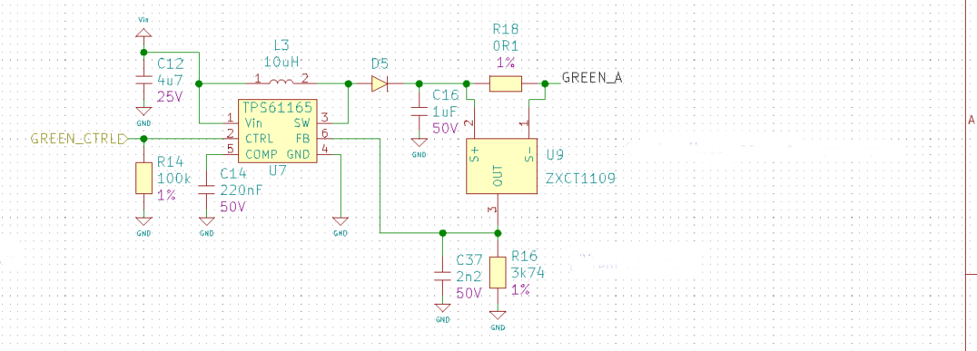
The 4x LED srings are wired as common cathod and return to the GND net, hence the use of the ZXCT device to provide high side current sensing.

  • Hi Nick,
    I have tried to understand your application, have you ever measure the inductor current waveforms when the error occurs? I suggest you to observe the waveforms whne it occurs error. And I have roughly calculate from your circuit, your maximim current for Green leds is about 125mA. I'm a little worry about maybe it has triggled the internal current limit whne you increase the duty cycle. BTW, what your input voltage level?
    Regards
    Sean
  • Hi Sean,
    Thanks for the reply. I'll try and measure the inductor current.

    The supply voltage is anywhere between 6 -> 8.4V as the product is powered from a 2S lithium battery pack. However I also observe this phenominon when powering the circuit from a bench power supply set to 8.3V

    Kind regards
    Nick
  • Hi Sean,
    I have attempted to measure the inductor current using a 0.01R resistor. The peak current appears to be 0.4A therefore considerably under the limit. However, given that the circuit is responding differently since the resistor was added I'm guessing that it has had some sort of limiting effect anyway.

    Measuring the current into the circuit from the power supply, at 8.36V supply, the circuit is drawing 76mA with the LEDs off and 188mA with the green LEDs at full PWM. Giving a current of 112mA being consumed by the driver and LEDs. This was measured without the 0.01R resistor inseries with the inductor.

    It does feel as though something is marginal, as we have some working boards and some exhibiting this issue.

    Kind regards
    Nick
  • Hi Nick,
    Do you have any update for your board? Can you measure what happended when the issue occurs? Usually when the brightness suddenly changed, it may caused by the current limit. So I need more information and waveforms to help you identify the question and solution. Thanks.
    Best Regards
    Sean