This thread has been locked.

If you have a related question, please click the "Ask a related question" button in the top right corner. The newly created question will be automatically linked to this question.

TPS23861: VDUV and VPUV error

Part Number: TPS23861

54Hi experts,

I'm using TPS23861 in my POE board, I found the PD would power cycle every a few seconds (e.g. 4 seconds).

Then I used my PROC to read back the register0 and register 0A, register 0 is 9f and register 0xa is 0x30, so both VDUV and VPUV are "1". 

In my board, VPWR (54V) will be ready 100ms earlier than VDD(3.3V), both SHUT_DOWN and RESET signals will be low, until CPU is up, SHUT_DOWN will be driven high firstly, then RESET signal.

Can you give me some comments why VDUV and VPUV are both "1"?

By the way, I think TPS23861 is working, as I could read 54V in registers 0x2e & 0x2f, read 25kohm resistor in 0x60 and 40degree in 0x2C.

Thanks
Chris


  • Hi Chris,

    Did you clear all event register after power cycle? The VPUV and VDUV are set by default and you need to read register 0x0B to clear the event after power cycle. For the port issue, I think the reason you see the port power cycling is because the PD doesn't provide valid MPS(maintain power signature) to the PSE and PSE disconnect the port when the current is too low. Can you measure the port voltage and port current on the scope and send me the waveform to verify? Thanks.

    Best regards,

    Penny

  • Hi Penny,

    Thanks for your comments.

    After reading register 0x0B, the VPUV and VDUV are fixed.

    As for the current, I have two test cases:

    1) the load is always 54.1V/34mA, the PSE is working, there is no power cycling.

    2) the load is 54.1V/34mA at the very beginning, then the CPU in load will turn on some components in it, so the current will go from 34mA to like 85mA, then I got the power cycling.

       The board is keeping power on/off, so the current is not stable, it could be any value between 0mA - 85mA, I measured more than 10 times, 85mA is the maximum I could get.

      I copied the value of some registers below:

    -  0x0, 1F, 

    - 0x1, E4

    - 0x2, 11

    - 0x4, 1F

    - 0x6, 10

    - 0x8, 00

    - 0xa 00

    - 0xC, 00, 44, 04, 06,  the value is changing.

    - 0x10, 00, 11, the value is changing.

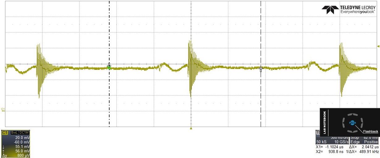
    Please refer to below for waveform. it's the voltage over two 0.51ohm resistors.

    Thanks

    Chris

  • Hi Chris,

    I think my original suspect is right. Just to clarify,for the first test case, is the 34mA a stable DC current?

    For the second test case, the current is pulsing  and looks like the current doesn't meet the MPS spec in IEEE standard(The MPS is an electrical signature presented by the PD to assure the PSE that it is still present after operating voltage is applied. A valid MPS consists of a minimum dc current of 10 mA (or a 10-mA pulsed current for at least 75 ms every 325 ms) and an AC impedance lower than 26.3 kΩ in parallel with 0.05 μF). As TPS23861 uses DC disconnect, the load should meet the DC current requirement for MPS. To quickly verify this, you can do one more tests:

    1. Add some dummy load to your board and keep the current highter than 10mA and see if the PSE port keeps on. 
    2. Disable DC disconnect in register 0x13 and rerun your second test case again and see if the port keeps on.

    Overall, the PD load didn't provide the valid MPS signal to keep the port on and the TPS23861's behavior is expected. Thanks.

    Best regards,

    Penny

  • Hi Penny,

    Thanks for your valuable input.

    For a minimum dc current of 10mA, that's 10mA x 0.255Ω = 2.55mV, so it means the voltage of two 0.51Ω resistors in parallel must be higher than 2.55mV, is that right?

    As for ac impedance lower than 26.3kΩ and in parallel with 0.05uF, is there a simple way to get this ac impedance? my load should be much higher than 0.05uF, will this be a problem?

    I'll make test next week and come back to you.

    Regards
    Chris
  • Hi Chris,

    You calculation is correct. Don't worry about AC impedance as our PSE device only use measures DC current to do the disconnect and it doesn't support AC disconnect. Thanks.

    Best regards,
    Penny
  • Hi Penny,

    You are right, after setting the 0x13 with 0x0, my PD can always be up.

    Last few questions from my side,

    - By writing 0x13 with 0x0, I only access register of TPS23861, not EEPROM, so I didn't have the 25 cycles limitation, is that right?

    - Can I just add a 5.4kΩ resistor between 54V and PSE_N[x] to add a dummy load? I'm using an electronic load and set it in Constant Resistance mode, but it seems it couldn't work.

    - By writing 0x13 with 0x0, is there any defects with this method, as I found the current for on channel will be "0"?


    Thanks for helping on this topic so far, your support is really key for me, I really appreciated.

    Regards
    Chris
  • Hi Penny,

    I measured the current of sense resistor using both oscilloscope and multi-meter, there is no chance its voltage will be less than 2.55mV, the minimum value of my board is like 21mV.

    In my board, I am using a boost circuit to generate 54V from 12V, so there is some noise in the waveform of R sense, please refer to below for details, will this noise cause the problem?


    Thanks
    Chris