This thread has been locked.

If you have a related question, please click the "Ask a related question" button in the top right corner. The newly created question will be automatically linked to this question.

BQ25504: Boost Converter in Operation???

Part Number: BQ25504

What is the best way to tell when the boost converter is running?

  • John,

    I recommend using an oscilloscope to measure the waveform on LBOOST. If it an intermittent square wave like d/s figure 16 then the charging is boosting.
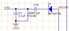
  • If you are asking about a signal to indicate boost operation, you can add something like the circuit below.  When CHG is high, the converter is boosting. When CHG is low, either charge is done or no power from input source (e.g. no sun for solar panel).  There will be an RC delay.

  • Hey Jeff, for some reason the graphic with the schematic isn't showing up.
  •  Sorry about that.  Please see attached file.

  • Thanks Jeff, one more question: What's the best way to verify that the MPPT function is working correctly?  I've got my resistor divider network set up to load the solar cell at about 75% of its open circuit voltage, but I'm not convinced it's actually operating at that point, my battery is taking WAY too long to charge from a cell that should be putting out plenty to charge it way faster if it's actually operating at its max power point.  Is there a good way to check where the IC is actually operating the cell?

  • John,

    You can use an oscope to measure the LBOOST pin and VIN_DC pin. If there is a square wave burst and the VIN_DC voltage starts higher and then drops to your expected MPP point, then the charger is working. See datasheet figure 23 on page 22 as an example.
  • I'm attaching a couple of scope shots (same signals, different time bases) if you wouldn't mind helping me make sense of them.  The yellow trace is the LBOOST pin, which seems to show the boost converter working well.  The blue trace is the VIN_DC pin, and I don't see much level shifting going on with that signal.  I'm not convinced that the MPPT function is working.  Am I looking at this correctly?

  • The switching waveform looks normal.  Is VINDC regulating to the MPP voltage you expect?  I would have expected a bit more ripple on VINDC like the datasheet waveform, as the input capacitor charges, discharges while switching and then recharges.

  • Jeff,

    That's exactly what I'm trying to understand myself.  My understanding is that the chip will periodically sample the open circuit voltage of the cell and then make some adjustment to how it loads the cell to ensure that it is being operated at the max power point as defined by the Roc1 and Roc2 resistor network.  I've got this network set up on my board to operate the cell at about 75% of the open circuit voltage, but as I said, I'm not convinced it's actually working there.  Looking at the VinDC waveform, it looks to me like the cell is just always being operated at the open circuit voltage, but I guess I wasn't 100% sure whether or not I could draw that conclusion from looking at that waveform.  Is there any better way to tell for sure where the cell is being operated during MPPT operation?

  • John,

    That's the definitive way. LBOOST should switch only while VIN_DC is above your MPP point and then stop when if it drops below it. If your source is low impedance (bench power supply) it will switch indefinitely. If you want to simulate your hiZ source, add a small-ish resistor in series with a power supply.

    You can't load the VREF_SAMP cap with a scope probe or multimeter but you can overdrive it will a power supply at the MPP voltage you desire. If VIN_DC does not regulate to that voltage while LBOOST is switching then there is a problem.