This thread has been locked.

If you have a related question, please click the "Ask a related question" button in the top right corner. The newly created question will be automatically linked to this question.

BQ24295: Charge Safety Timer Expiration fault in REG09

Part Number: BQ24295

Dear Sirs:

I have a question for Charge Safety Timer Expiration fault.

When would it be triggered and cleared?

We set the CHG_TIMER(REG05) to 5 hrs and enable Charging Safety Timer(EN_TIMER:1).

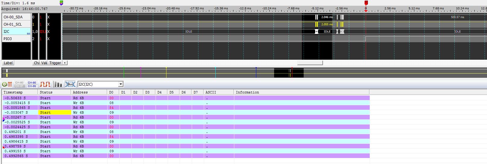
Polling the System Status Register(REG08) and New Fault Register (REG09).

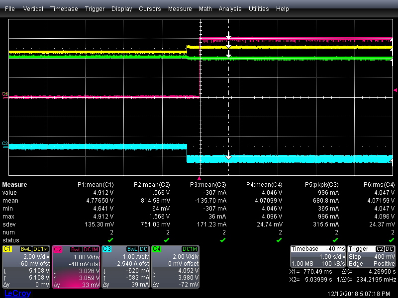
After charging 5 hours, the value of REG08 change from 0xAC to 0x84(Fast Charging to Not Charging).

The Charge Safety Timer Expiration seems triggered, hence it stops charging.

But CHRG_FAULT does not change anymore.  We try to read the REG09 many times and it is always 0.

How can I know the  Charge Safety Timer Expiration fault happened?

Best Regards,

  • Hey Miya,

    The CHRG_FAULT should report at least once that the Safety Timer Expired if that fault triggers. The fault will clear if read a second time.

    Another point to consider is successive faults. This device will only latch the most recent fault to the charger, meaning if the Safety Timer expires and then another fault appear after, only the second fault will be latched and reported on the next read of the register.

    And lastly, the fault register REG09  does not support multi-reads. It has to be read as a single byte, so make sure your polling does not attempted to read from both registers from a single command.

    Regards,

    Joel H

  • Dear Joel:

    Thanks for your reply.

    There is no error fault is triggered, since the value of fault regester REG09 is 0 in the period.
    We read signal byte by indenpendent command for every register. We check we can read realted bit for other fault case, EX:NTC_FAULT.
    But we still can not read the fault for Safety Timer Expired.

    May you help to check there is other possible reason for the Safety Timer Expired fault?


    The all register settings are as below:
    {
    0x4C, /* reg 0 - VIN:4.56V,Divider 3:1A */
    0x10, /* reg 1 - Charger Enable,SYS_MIN:3V */
    0x40, /* reg 2 - external ilimCharger with 1536mA current limit */
    0x00, /* reg 3 - Pre-charger current=128mA, Terminal-128mA*/
    0xCB, /* reg 4 - Charger voltage-4.304,recharger:below 300mV*/
    0x88, /* reg 5 - I2cWatchdogT0x00-dISABLE,Enable Safety Timer-0x1, Fast charging timer:5 hours */
    0x91, /* reg 6 - Thermal regulation threshold:80'c*/
    0x88, /* reg 7 - DPDM_EN-0x1, TMR2X_EN:0x0,Turn on BATFET, NO INT */
    };

    We don't use INT, hence it is disabled(INT_MASK[0]/[1] = 0 on REG07). Does it influence the value of fault Register?

  • They Miya,

    This should not affect the value of the FAULT register. Masking the /INIT pin would only prevent the 256us pulse from outputing on the pin.

    Can you rerun your test and trigger on the battery charge current going to zero? I want to see the input voltage, battery voltage, and battery charger current (trigger). If you can also read twice immediately after this event occurs, showing either the SDA waveform or a datalog of the register dump, that would be helpful.

    One theory is another fault triggering and clearing from the transient event of the charge disabling.


    Regards,
    Joel H
  • Dear Joel:

    Get the scope with below signal:

    PIO3 is our trigger signal as the CHRG_STAT(REG08) change  to 00(Not charging) from 10(Fast Charging) .

    Yellow curve: VBUS

    pink curve: PIO3

    blue curve: current of battery

    green curve: voltage of battery

    We also capture I2C data with Acute Logic Analyzer .

    The file with .law, you can download related LA viewer tool from Acute web. I also export the I2C data to I2C_TimerExp_20181212.csv. (The attached file LA data.rar)

    We read the reg_08->reg_09->reg_09->reg_08->reg_09->reg_09, the value and data as below:

    Sample Status Address D0
    -1016036 Start Wr 6B 08 
    -1015181 Start Rd 6B AC 
    -1014154 Start Wr 6B 09 
    -1013901 Start Rd 6B 00 
    -1013671 Start Wr 6B 09 
    -1012660 Start Rd 6B 00 
    -10683 Start Wr 6B 08 
    -10373 Start Rd 6B 84 
    -6134 Start Wr 6B 09 
    -5340 Start Rd 6B 00 
    -5105 Start Wr 6B 09 
    -4885 Start Rd 6B 00 
    996402 Start Wr 6B 08 
    996679 Start Rd 6B 84 
    997283 Start Wr 6B 09 
    997518 Start Rd 6B 00 
    998306 Start Wr 6B 09 
    998573 Start Rd 6B 00 

    LA data.rar

  • Hey Miya,

    You are going to hate me, but I need to see a more zoomed in waveform of this event. Right now you have it as 1s/div which is way too long to capture a transient like the one I'm looking for. Trying 10ms/div to 100ms/div. For PIO3, how far between in time are the register reads? Is your excerpt of the datalog in sec, ms, us? I am trying to get a feel for where on this waveform each successive sample of the charger data is being taken.

    Regards,
    Joel H
  • Dear Joel:

    For the scope, we uploaded related file. Please check it.cc10.rar

    For I2C data, you can check the .law file with acute LA viewer directly. There is timing sequence for PIO3 and I2C data. As below.

  • Hey Miya,

    I am not familiar with the software you recommended but from what I can tell, the data only goes back ~500ms from your trigger point. And then it immediately jumps to your trigger point at around time zero.

    This is why we need trigger on the battery current falling edge zoomed in time. I suspect some other event is occurring when this transition is happening.


    Regards,
    Joel H
  • Hey Miya,

    To add to my previous reply, I also saw the waveforms in your most recent captures, but I need to ask if these are just zoomed of the previous ones or are they taken at the new time scale? I ask because there is a small spike in the battery voltage that I want to analyze in conjunction with the VBUS waveform.

    I think we need to see something more zoomed in, about 100 us time frame just to be sure.


    Regards,
    Joel H
  • Dear Joel:

    Sorry, I don't understand your point.
    From the I2C log, if there is other fault, we should read from fault register.
    According the log, we read REG_08, the status keep in charging(0xAC), and read REG_09 for twice, the value is 0.
    After 500ms, we read REG_08, the status changed to non charging(0x84),and read REG_09 for twice, the value are still 0.

    The timing is all for 5 hours for the issue and we set the Fast charging timer:5 hours.
    May you describe what kind of problem you guessed? Is there any reason MCU can not know the status from I2C register?
    Since we can not setup test environment now, may you check your requirement first?
    100 us? It seems to short.
    Thank you.
  • Hey Miya,

    Yes, I'm just concerned when the charge current goes to zero, that sudden transient step is forcing another fault or some POR condition meaning that in between reads, the device is reset. I good way to check this is to see whether the settings you programmed on the charger before the timer expires match the settings after.

    My point about the log sampling rate is that the transient event can be much faster than 500ms and trigger a device reset.

    I wanted to look at a very zoomed in waveform (100us is an estimate now, maybe even shorter) to see if VBUS, VBAT, or both drop too low after this event.


    Regards,
    Joel H
  • Dear Joel:

    We read back the REG_04 after the issue occurred, and thee register value is same with our settings - 0xCB.

    The charging IC seems not reset. The default value of REG_04 in charger IC is 0xB2 not 0xCB.

    We get the SCOPE with 200us/div and trigger with charger current. Triggered with charger current. PIO3 does not connect.

    The related wave file. 

    200us_wave_20181217.rar

  • Hey Miya,

    Your waveform looks fine. There is nothing to suggest the charger going into an OVP/ULVO condition on either VBAT or VBUS.

    I will run a similar test on the BQ24295EVM and get back to you. We know the charge safety timer expiration trigger a fault.


    Regards,
    Joel H
  • Hey Miya,

    So I tested the safety timer overnight and it triggered correctly and when I read the registers, I could see the fault in the FAULT register 09. I read B0, which equates to a Watchdog Timer fault (occurs because this was the first write into the device to host mode) and Charge Timer Expiration. And even after continual reads, while the Watchdog Timer fault went away, the Charge Timer Fault remained.

    The difference between my setup and yours is that my I2C read did not come until after it had already expired.

    One point I forgot to ask about is the STAT pin. Have you monitored the STAT pin after the charge stops? When this fault occurs, the STAT pin oscillates at 1 Hz to indicate a fault present. So after the fault, this pin should be changing states.


    Regards,
    Joel H
  • Dear Joel:

    May you use the same setting with us to test? Or do you know any setting would influence the fault?

    We don't enable the watch dog timer.

    The all register settings are as below:
    {
    0x4C, /* reg 0 - VIN:4.56V,Divider 3:1A */
    0x10, /* reg 1 - Charger Enable,SYS_MIN:3V */
    0x40, /* reg 2 - external ilimCharger with 1536mA current limit */ 
    0x00, /* reg 3 - Pre-charger current=128mA, Terminal-128mA*/
    0xCB, /* reg 4 - Charger voltage-4.304,recharger:below 300mV*/
    0x88, /* reg 5 - I2cWatchdogT0x00-dISABLE,Enable Safety Timer-0x1, Fast charging timer:5 hours */
    0x91, /* reg 6 - Thermal regulation threshold:80'c*/
    0x88, /* reg 7 - DPDM_EN-0x1, TMR2X_EN:0x0,Turn on BATFET, NO INT */
    };

    No, we don't monitor the STAT pin.

  • Hey Miya,

    Are you asking for the test setup I used? If so, I used the default charging (no communication) with 5V input on VBUS and a battery simulator (bidirectional power supply Keithley 2420) set to 3.5V fixed with a large 100,000uF capacitor in parallel at the BAT pin of charger. This was all done the BQ24295EVM. I short D+/D- pins to get the maximum input current.

    Can you run your test and monitor the STAT pin to see if it oscillates at the 1 Hz frequency after the charge goes to zero?


    Regards,
    Joel H
  • Dear Joel:

    Can you also set the settings I provided on above reply to test?

    I want to check it is caused by setting or not. You keep charger IC in default mode with default setting.

    According our setting, it would keep in host mode with our settings.

    Please help to check. Thank you.

    We have setup the environment to check the STAT, but we still need to check why the fault register can not be read.

  • Hey Miya,

    We will investigate using your configuration. 

    Please also check the behavior of the STAT pin when the fault occurs in the meantime. 

    Regards,

    Joel H

  • Hey Miya,

    I believe the issue is coming from this line:
    0x88, /* reg 7 - DPDM_EN-0x1, TMR2X_EN:0x0,Turn on BATFET, NO INT */

    specifically the NO INT. Are you disabling the INT_MASK[1:0]?


    Regards,
    Joel H
  • Dear Joel:

    Sorry, I am confused.

    Yes, we disable the INT_MASK[1:0]

    We asked in previous reply on Dec. 4 and you replied it would not influence.

    Miya: We don't use INT, hence it is disabled(INT_MASK[0]/[1] = 0 on REG07). Does it influence the value of fault Register?

    Joel:This should not affect the value of the FAULT register. Masking the /INIT pin would only prevent the 256us pulse from outputing on the pin. 

    May you teach us how to modify? Just enable the INT_MASK[0][1], but we don't monitor the INT pin, is it OK?

  • Dear Joel:


    Sorry, I am confused.

    Yes, we disable the INT_MASK[1:0]

    We asked in previous reply on Dec. 4 and you replied it would not influence.

    Miya: We don't use INT, hence it is disabled(INT_MASK[0]/[1] = 0 on REG07). Does it influence the value of fault Register?

    Joel:This should not affect the value of the FAULT register. Masking the /INIT pin would only prevent the 256us pulse from outputing on the pin.


    May you teach us how to modify? Just enable the INT_MASK[0][1], but we don't monitor the INT pin, is it OK?
  • Hey Miya,

    I was mistaken that it would not affect the FAULT register. This behavior needs to updated in the next revision of the datasheet.

    The INT_MASK bits affect the FAULT register reporting. You should be able to disable the mask and allow INT for those two registers to get the appropriate behavior. Please try this and let me know. There is no impact if you do not monitor the /INT pin.


    Regards,
    Joel H
  • Dear Joel:

    I can read the Charge Safety Timer Expiration fault after enable the INT_MASK.
    But I have one more question, how can I clear the fault?
    I try to disable/enable charging by set CHG_CONFIG(Bit 4 on REG01) to 0 and 1, but the fault still keeps and it can not recover to charging status.

  • The safety timer fault should clear after toggling the CHG_CONFIG bit in REG01. You should be able to read the Fault register twice the fault should be removed.

    You can also toggle REG05[3] to disable and re-enable the safety timer or toggle the /CE pin from a logic LOW state to a logic HIGH.


    Regards,
    Joel H
  • Dear Joel:

    I try to read many times after toggle the CHG_CONFIG bit in REG01 but the fault REG does not clear.

    I try to disable/enable the BATFET(Bit 5- BATFET_Disable) too and the fault would be cleared after disable BATFET.

    It also can recover to charging status.

    I would use the BATFET_Disable bit to recover, if you have other concern please let us know, Thank you.

  • Hi Miya,

    Sorry for the delayed response due to the holiday.

    I would suggest toggle REG05[3] to disable and the enable the Charging Safety Timer to clear the fault. On the other hand, it looks like the safety timer setting should be longer than your current setting. The timer can be adjusted by REG05[2:1].