This thread has been locked.

If you have a related question, please click the "Ask a related question" button in the top right corner. The newly created question will be automatically linked to this question.

UCC2897A: Inquiry for the relationship between main FET switching and output inductor

Part Number: UCC2897A

Hi team

My customer designed the circuit with reference to PWR758.

Increasing the output load as shown below changes the Vds value of the switching FET.

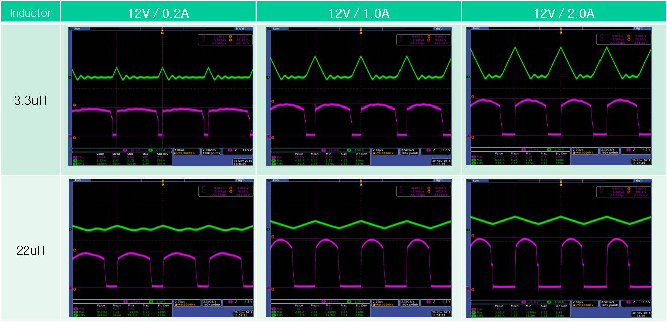
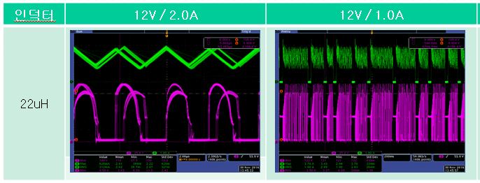
- Pink : Vds(Switching voltage for FET) / Green : Inductor Current

The PWR758 EVM does not change the switching voltage(Vds) even when the output load varies.

When the output inductor is subjected to aging test with 22uH applied, the transformer generates heat and a switching oscillation occurs.

The circuit diagram and each measurement point are shown below.:

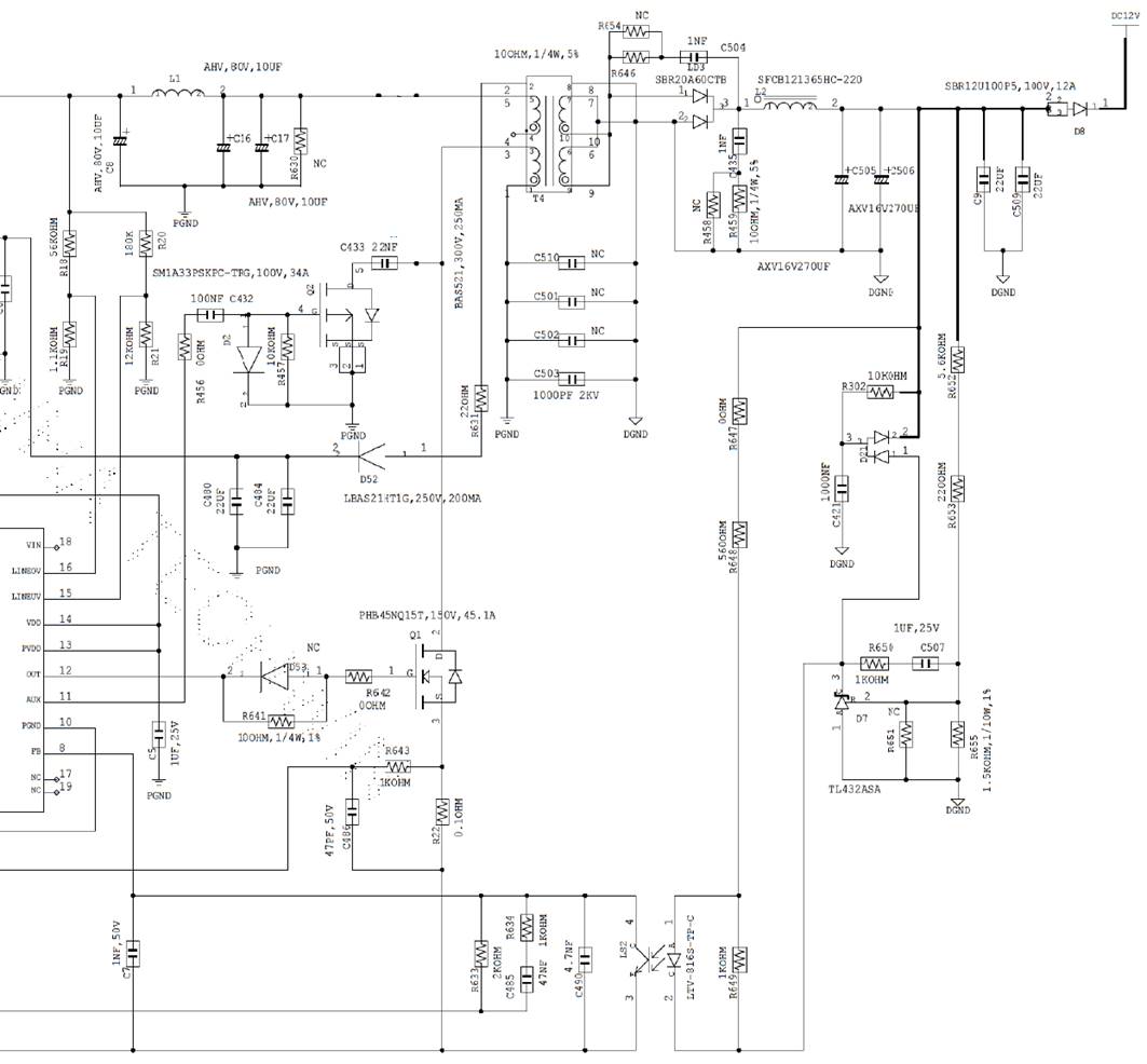
The pin map of the transformer is different using the circuit library I used.

Please refer to the following for transformer information.

Please check and reply the following :

1. Why the Vds of the UCC2897A FET changes when the output inductor is changed?

2. Is it normal for FET Vds to change with load variation?

3. Is it normal for switching duty to change with load variation?

4. What is the cause of transformer heat generation and FET oscillation?

  • Hi Charles,

    Sorry for the late response, I have contacted one of my colleagues to answer this question.

    Regards,
    Teng
  • Hi Charles,

    Please see below for my reply.

    1. Why the Vds of the UCC2897A FET changes when the output inductor is changed?

    Frank: By looking into the first group of waveforms you attached, it seemed that the primary duty cycle are different in use of different output inductors. It may be caused by larger DC voltage drop by using larger inductance output inductor. The average Vds of primary low side NMOS are determined by Vin/(1-D), where Vin is input voltage and D is the duty cycle of Primary low-side MOSFET duty.  Therefore, different duty cycle results in different voltage stress.

    2. Is it normal for FET Vds to change with load variation?

    Frank: Yes, because the load variation will cause duty variation. 

    3. Is it normal for switching duty to change with load variation?

    Frank: Yes, because the load variation will cause the DC voltage drop variation on the route from input to output. This voltage variation drop should be corrected by Duty variation. 

    4. What is the cause of transformer heat generation and FET oscillation?

    Frank: Transformer heat consists of winding loss including both DC and AC copper loss and magnetic core loss which is majorly magnetic hysteresis loss if it is ferrite core. The FET oscillation may be associated with the design of compensation loop and noise injection. In order to remove the oscillation, the phase margin of the loop should be larger than 40 degree and no noise coupled to feedback loop.    

  • I can not calculate phase margin.
    I request a circuit review.
    Please let me know your e-mail address and I will share the circuit.
    Customers are complaint with the delay in technical support.
    Please check the circuit reviews and constants that do not generate heat.
    Thank you.
  • Charles,
    Could you send me a email to Frank-tang@ti.com, then I will introduce you to the AE expert who is responsible for the customer support of this part.
    Best Regards
    Frank
  • Hi Frank
    I'll check out just a few of the questions above.
    1) Is it normal for the value of the output inductor to affect the Vds and Duty of the FET change much?
    2) Adjusting the Duty time by change the turn ratio of the transformer can help solve the heat problem?
    Thank you
  • Hi Charles,
    For your questions, see below for my answer
    1) Is it normal for the value of the output inductor to affect the Vds and Duty of the FET change much?
    Frank: The duty cycle change and Vds change depend on the DC resistance difference between two inductor.
    2) Adjusting the Duty time by change the turn ratio of the transformer can help solve the heat problem?
    Frank: Sometime it could. I recommend to design turn ratio to get around 0.65 maximum duty cycle in all operating condition.
    Thank you