This thread has been locked.

If you have a related question, please click the "Ask a related question" button in the top right corner. The newly created question will be automatically linked to this question.

BQ24296: Bq24296 power Manager

Part Number: BQ24296

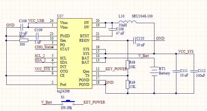
HI. I use Bq24296 as a voltage Converter from the battery to the system and as a battery charger. The scheme is typical, taken from the Datasheet. There is no register management and configuration(default mode). The system output voltage is 3.2 Volts, although it should be 4.2 V. and a very small current-a few microamps.  The battery is not charged when the voltage is connected to the Vbus input. There is no reaction to the closure of the qon input(pin 12). What could be the problem? How to configure?

  • Hey Enot,

    Please refer to section 10 Application and Implementation of the datasheet to compare your schematic against.

    We typically suggest between a 1.0uH and 2.2uH inductor. In your application, the resonant frequency of the output filter of the converter is well below what the IC is compensated and designed around.

    Let's start there. Please also make other changes based on the suggestions in that section.


    Regards,
    Joel H
  • According to the scheme:
    1. Installed signal lines of configuration ILim, OTG, CE, Psel
    2. I do not use thermal resistance in TS circuit. Recalculated the parameters of the resistive divider to be similar to the average temperature.
    3. The inductance was changed to 2.2 uH. The result hasn't changed.
    It is necessary to understand why the LDO stabilizer does not work at the start of the system. The SYS output voltage drops at any load in the circuit. When connected, the LED voltage drops to 1.5 V, indicating a small, insufficient current (<1mA). Qon input does not work-output parameters are not changed when closing to Vbatt..
  • Hey Enot,

    I would also recommend putting more capacitance on the PMID in accordance with the datasheet requirement of at least 8.2uF. You currently only have 1uF.

    With the 2.2uH inductor, I would also recommend decreasing the output capacitance on VSYS, as you are still pushing the resonant frequency of the output filter below the design recommendation of 15kHz.

    Please also provide a waveform of your output at VSYS.


    Regards,
    Joel H
  • Chip needs to produce the voltage VSYS when connected to the battery(Vbatt) and when you turn off Vbus? There is no voltage on Vsys now.
  • Hey Enot,

    The charger only regulated VSYS when there is power to VBUS. Without VBUS, VSYS will not be regulated but rather it will follow the battery voltage with an IR drop down to approximately 2.5V


    Regards,
    Joel H