This thread has been locked.

If you have a related question, please click the "Ask a related question" button in the top right corner. The newly created question will be automatically linked to this question.

LM3150: Jitter in switching frequency

Part Number: LM3150

Hello,

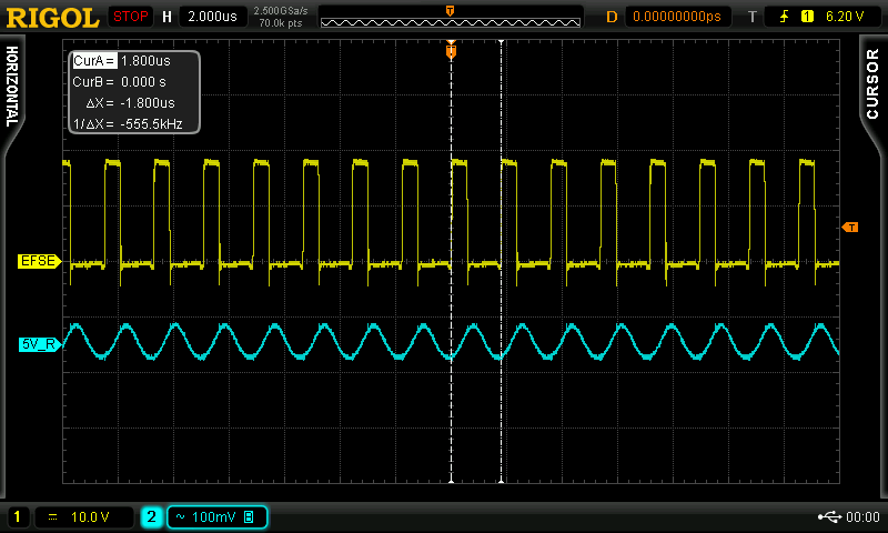
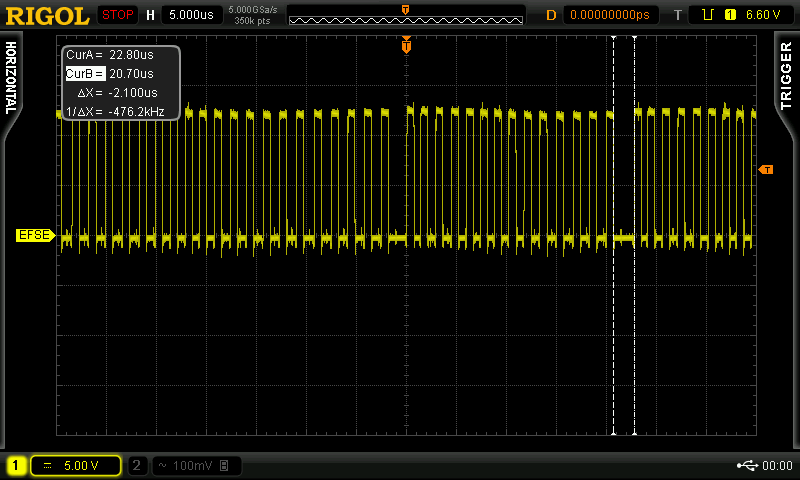
I have used LM3150MHX/NOPB as a buck converter for 5V/15A output with the input varying from 9V to 15V. The switching frequency is calculated to be 500KHz. I have used WebBench simulation tool for reference. However I have observed a jitter in the switching frequency at the SW pin.The ON time remains constant but the OFF time varies continuously which results in the variation of switching frequency. This results in higher ripple voltage of around 70mV to 130mV depending on load current. I have attached a oscilloscope screenshot of the switching waveform. Can you please suggest some advice as to why the frequency is changing or how to prevent it?

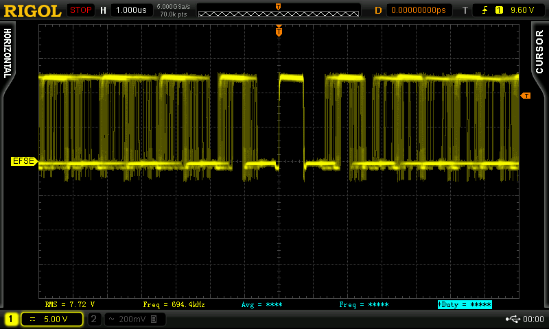
Also, I have observed that there is a large OFF time of around 1.3uS to 2uS which occurs randomly, even though the output is loaded with 3A. I have attached the screenshot of the waveform which shows this. Can you please give an insight to this matter?

Thanks,

Bhargav Saikia

  • Bhargav Saikia,

    I believe there may be 2 issues at play here:

    1. The layout or component selection couples noise into the FB pin which causes this apparent instability. Please share your schematic and layout so I can take a look.

    2. You may be running into Toff-min which could explain the skipped pulse. Does the skipped pulse go away when you increase the input voltage?

    -Sam
  • Thank you Samuel.

    I have observed the following.

    1) The skipped pulse becomes wider and occurs more frequently at higher input voltages. At 15 volts or higher the Toff pulse width becomes almost 5uS and appears very frequently. But at lower input voltage of 10V, the skipped pulse disappears. At typical input voltage of 12-13V, the Toff pulse width is around 1.3us to 2uS and occurs somewhat less frequently. The jitter also becomes less at low input voltages of 9V to 10V.

    2) Regarding the jitter and varying switching frequency, I have observed that the switching frequency becomes stable (very less jitter) at a narrow input voltage window of around 16.8V to 17.2V. It depends on load current too. If we say the frequency is stable at 16.9V, then increasing the load slightly, say 5A to 5.2A the frequency again becomes unstable and the jitter reappears. At that moment, if the input voltage is increased slightly, from 16.9V to 17V the jitter disappears. Again increasing the load to 6A brings back the jitter while again increasing the input voltage to 17.1V kills the jitter. But at voltages of 15V or 19V, the jitter appears again and there seems to be no effect of load current on it. The Rds-on of the LOW FET is around 3.7mohm to 5mohm.

    I have attached the schematic and layout of the design. Please note that the Cff value used now is 100pF instead of 1200pF which is in the schematic design.

    1) Assembly TOP

    2) Layout - TOP Layer

    3) Schematic Design

    Thanks,

    Bhargav

  • Bhargav ,

    Typical COT hysteretic controllers need a significant amount of output capacitor ESR to maintain a minimum amount of ripple at the FB pin in order to switch properly and maintain efficient regulation.

    As you can see from the Switch node waveform that the switching is not stable .

    You may need to add a ripple injection circuit for this design . Follow the appnote for more detail .

    http://www.ti.com/lit/an/snva166a/snva166a.pdf 

    Further you can use Webench and under advanced tab choose Low O/P ripple option to design ripple injection circuit.

    Further please ensure that the noise sensitive return path first see the SGND then PGND . See how the feedback return path as well as soft start cap return path is first seeing SGND and then getting connected to PGND . 

    ---Ambreesh 

  • Hi Ambreesh,

    Thank you for your valuable suggestion. I have tried implementing the ripple injection circuit as per the app note which link you have sent. The calculated values are 250K, 330pF and a 1uF capacitor is used for coupling the ripple. However, the practical values I have used are 249K, 470pF and 1uF.

    After implementing this circuit there was improvement in the jitter response, but not totally absent. However, when a (1 to 15)Amp transient was carried out @ 0.1A/uS the voltage drop was worse compared to when a single Cff of 100pF was used. The voltage dropped by around -200mV before going to settle at -85mV (this was observed in AC mode coupling of the scope).

    So, I tried using both the ripple injection circuit and the Cff of 100pF. To my surprise, the jitter was completely gone and the switching frequency was completely stable over the entire range of input voltage and load current. However the transient response didn't improve. When only the Cff of 100pF was used, the voltage dropped by only -110mV.

    Can you comment whether it is okay to include both the Cff and ripple injection circuit in conjunction? And please suggest some measure as to how to reduce the transient voltage drop?

    Thanks,

    Bhargav Saikia

  • The coupling Cap Cac values seems to be calculated wrongly use something like 3.3nF or so for the application . The ripple injection circuit should be enough for maintaining stable operation . You can increase the ripple by decreasing the Rr resistor (249K to somethign like 150K or so) .

    ---Ambreesh
  • Thanks Ambreesh,

    In the app note it is said that the coupling cap Cac should be 3 or 4 times larger than the integrating cap. I have used 470 pF for the integrating capacitor. So, 3.3nF or 4.7nF for the coupling capacitor should be fine. In the app note also, Cac is used as 0.01uF. But in Fig. 11, C8 is shown as 2.2uF. So, I thought of using a 1uF capacitor which would provide less impedance to the ripple and I thought would couple more effectively. I will try Cac of 3.3nF.

    However, my question was is it okay to use both the ripple injection circuit (consisting of 250K, 470pF and 1uF) and the Cff of 100pF in parallel with Rfb1. That made the frequency stable but I don't know whether is it advisable to do so. Please help.

    Thanks,

    Bhargav.

  • Bhargav,

    Cff here in the case of COT is not like typical feedforward capacitor . It basically results in limited increase in the AC ripple on the feedback . With implementation of ripple injection circuit you should be able to control the ripple injected on the feedback and it should be sufficient to make stable switching . Hence was my suggestion to remove the Cff and may be increase the ripple injected by modifyng the circuit itself .

    Ambreesh
  • Thanks Ambreesh,

    I will definitely try this. I am still not sure whether the jitter might be because of layout issue or an issue with component values. I will try all combinations.