This thread has been locked.

If you have a related question, please click the "Ask a related question" button in the top right corner. The newly created question will be automatically linked to this question.

TINA/Spice/TL431: How to simulate TL431 open loop gain, phase vs frequency chart in following circuit

Part Number: TL431
Other Parts Discussed in Thread: TINA-TI,

Tool/software: TINA-TI or Spice Models

Hello,

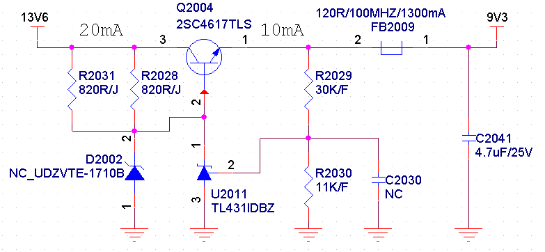
Customer find triangular wave added on DC output of the following circuit. The ac wave Vpp is about 100 mV and the frequency is tens of kHz. But when a capacitor of 1500pF is placed between PIN1 and PIN2, the output is normal.

How can I simulate the open loop of gain, phase vs frequency chart when added a cap between PIN1 and PIN2? 

Where should I break to realize a open loop when added a cap between PIN1 and PIN2?

slvm164.TSC

  • Hi Jeff,

    Figure 10 on the datasheet shows open loop for TL431. Is there a reason you need to do open loop in your circuit here? I typically see closed loop to see the response of the system.

    Cap between pin 1 and pin 2 is typically there for stability purposes.
    Also keep in mind that the circuit configuration you have above will make the TL431 more unstable. The Q2004 acts like an amplifier and amplifies the unstable region of the TL431 which can make the value of 4.7uF be too small.

    -Marcoo
  • Hello Marcoo,

    The circuit is mainly based on figure 33 of TL431 datasheet. According to my simulation, change 4.7uF to 10uF or series a resistor to increase ESR both increase stability. Is this make sense?
  • Hi Jeff,

    Both of those solutions can work. Unless you have very specific startup or noise requirements, I would recommend increasing the cap instead of increasing the ESR.

    -Marcoo