This thread has been locked.

If you have a related question, please click the "Ask a related question" button in the top right corner. The newly created question will be automatically linked to this question.

WEBENCH® Tools/TPS5430: 5V Output is not stabilized when applying a 500mA load.

Part Number: TPS5430

Tool/software: WEBENCH® Design Tools

Hello,

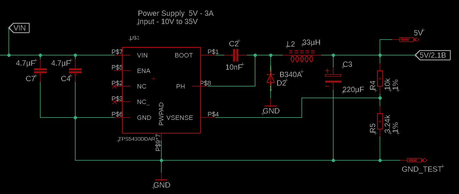
I implemented your design of the power supply TPS5430 from your example in the datasheet of the component.

  • Vin - 10V - 35V
  • Vout - 5V
  • Iout-max = 3A

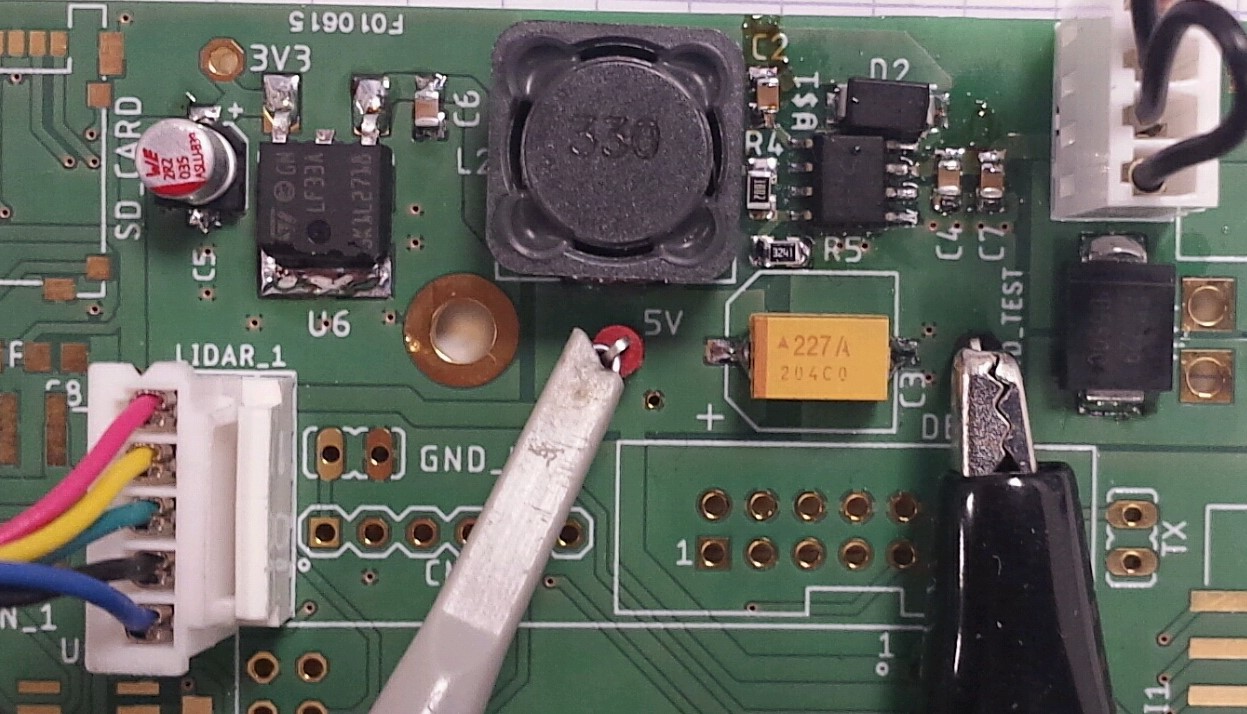
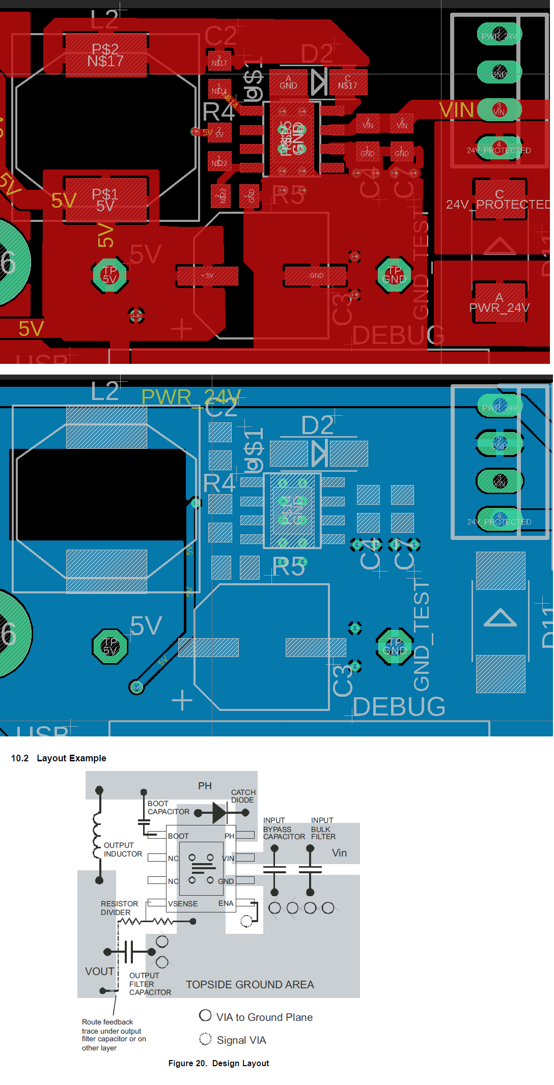
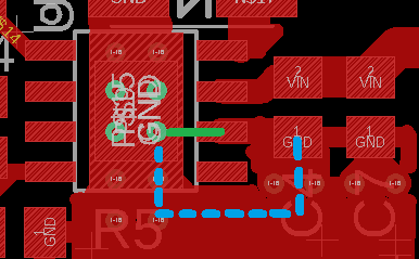
I also implemented the PCB layout recommended in the datasheet.

When I switch on the Vin = 24V, without any load, Vout is stabilized at 5V.

With a little load of 100mA, the Vout is still stabilized in 5V.

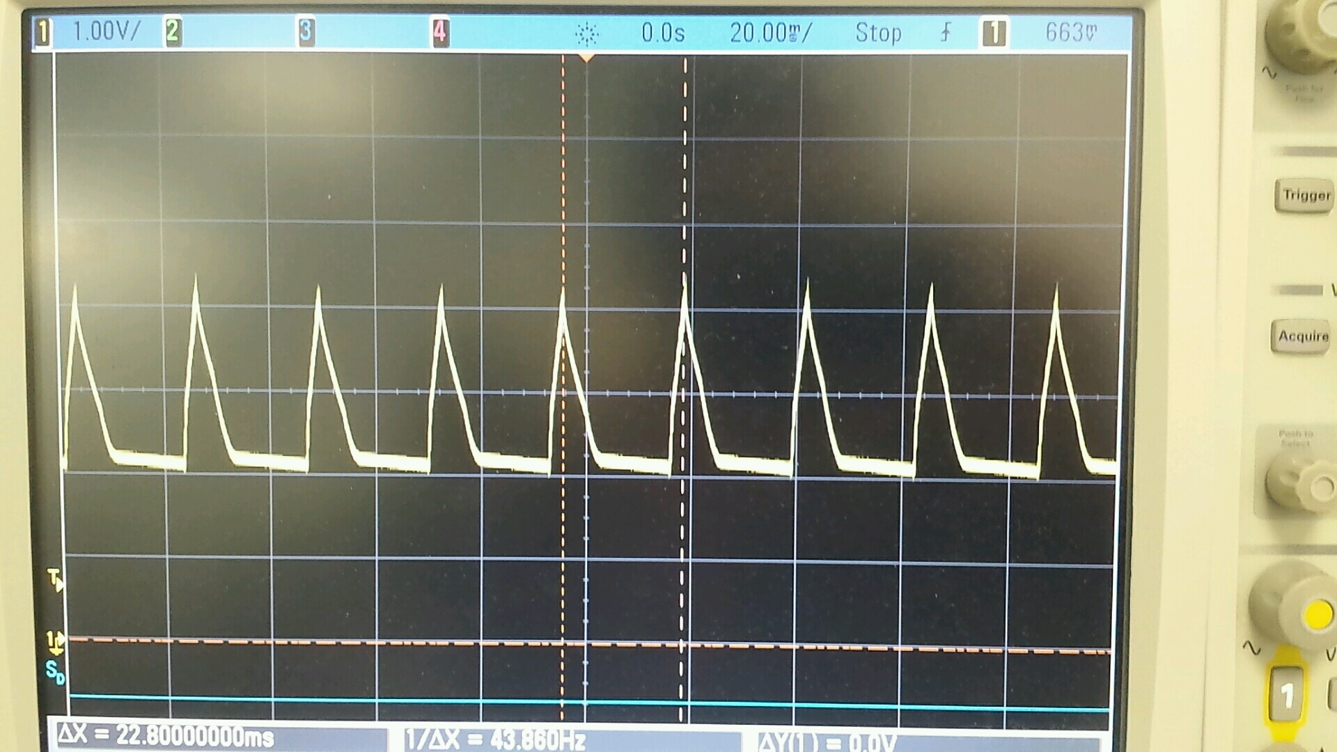
But when I apply a 500mA load, the Vout is not stabilized any more, see the attached picture.

Here are the components used in my design:

  • Cboot = 10nF (ceramic capacitor 0805)
  • L = 33µH : BOURNS SRR1260A-330M - farnell reference : 2374128.
  • Cout = 220µF Tantalum AVX TPSE227K010R0100 - radiospare ref: 135-9974.
  • D : B340A
  • Cin: 2 * ceramic capacitor 4.7µF

Would you have an idea of the reason for this issue ?

Regards,

Tantale AVX, 220μF, 10V cc,ESR 100mΩ

  • Matthias,

    It looks like it's hitting over current protection and entering hiccup mode (shuts off for 13-20 msec and tries again). Please share the schematic and layout so we can find out what's causing this.

    Thanks,
    -Sam
  • Good morning Sam,

    Thank you for your answer.

    Please find the schematic and the layout below:

  • Matthias,

    Your design does a very good job following the instructions we've given. This is interesting that it has this issue. I have a few thoughts:

    1. The GND pin is not connected to the thermal pad under the IC. Can you try reworking the board to connect this?
    2. Please confirm that ENA is floating. The top layer looks close.
    3. Try increasing the boot cap to 0.1uF.

    -Sam
  • Sam,

    Thank you again for your analyse.

    1: "The GND pin is not connected to the thermal pad under the IC": do you mean I should do the green path instead of the blue path ?

    2: Yes the GND is very near the ENA, but I checked it: the ENA is floating. I measured ENA = 5V when the power supply is switched on.

    3. I replaced the Cboot with a 0.1µF, I didn't notice any difference.

    I performed more tests.

    I succeed to have a 5V in the output with a 9 Ohm Load resistance. Iout = 555mA.

    But with a 3 Ohms Load, the output is not stable --> same issue.

    I also tried to connect my device (Lidar) which has a capacitive load, and it consume 500mA max. And I also have this issue connecting the lidar.

    I tried to reduce the capacitor from 220µF to 100µF but there is still the issue.

    I tried with another type of inductance (same value "33µH"), but it didn't solve the issue.

    Regards,

  • Matthias,
    1. Adding the green path is recommended but probably not what's causing this issue. It is still worth a try, though.
    2. Okay.
    3. Okay.

    What did you do to get the 555mA load to work?

    -Sam
  • Matthias,

    Do you have a scope shot of the input voltage? If wires are long and input capacitance is small, there can be large deviations in input voltage. It looks like your converter can be drawing a few Amperes during startup. What is your supply’s current limit set to?

    Regards, Robert
  • Good morning Robert,

    Here is my configuration:

    - wires are 1 meter long
    - Cinput : 4.7µF + 22µF ceramic
    - Power supply: 24V - 2A max
    - Imax TPS5430: 3A

    I've reduced the lenght of the wires to 30cm and I've added a 330µF electrolytic capacitor in the Vin to do test --> it has solved my issue !

    I drived 2A and my lidar sensor.

    Thank you so much for your support.

    Regards, Matthias