This thread has been locked.

If you have a related question, please click the "Ask a related question" button in the top right corner. The newly created question will be automatically linked to this question.

TPS65218: About the Ripple of DCDC4 for D0 and B1

Part Number: TPS65218
Other Parts Discussed in Thread: AM4372, , , TIDA-00606

Hi Sir 

We used AM4372 with TPS65218D0 for design and follow the EVM design.

We did the dynamic load test and found  the ripple of DCDC4 is all over 260mV in D0 or B1

Test Condition:  0.22A~0.88A; 0.8A/us.

Could TI  oofer  the test report, e.g. test waveform? or other suggestion ?

BR

Yimin

  • Hi SIr 

    1. DCDC4 Register(subaddress = 0x19) had been set to 0x32h. -> force PWM

    2. schematic is as follows


    3. Waveform


    BR

    Yimin

  • Hi Yimin,

    The TPS65218D0 applications lead is out of office, returning on Wednesday; please expect a more detailed response when he returns.

    In the meantime, what input voltage are you using, where you are probing, and are you using a differential probe? Do you happen to have a TPS65218D0 EVM you can compare results with?
  • Hi Sir

    Please offer the test report of DCDC4 for TPS65218D0 version.

    Waiting for your suggestion

    Thanks.

    BR
    Yimin
  • Yimin,

    What is the full part number of the TPS65218D0 device you are using? TPS65218D0RSL or TPS65218D0PHP?
  • Hi SIr

    1. TPS65218D0RSLR

    2. We measure waveform on R228 and input voltage is 5V

    3. Does TI have dynamic load test data, e.g. test waveform..

    BR
    Yimin
  • Yimin,

    The TIDA-00606 reference design test report is a good resource for test data on DCDC4.

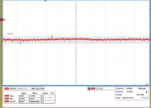
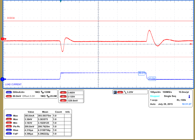
    Attached for your convenience are the two scope shots relevant to this discussion:

    • DCDC4 static ripple measurement

    • DCDC4 dynamic load response from 10mA to 400mA

    This data, taken on the TPS65218EVM-100, is consistent with your observations. Your load step is larger than the load step recorded in the TIDA-00606 test report, so it is expected that the voltage transient would also be larger.

    The output capacitance on DCDC4 is 47uF + 100nF on the EVM, but this value can be increased up to 100uF according to the DCDC4 COUT (max) spec in the datasheet. If you are using ceramic capacitors, a voltage rating of up to 10V or more would be best to account for de-rating when 3.3V is present at the DCDC4 output.

    Keep in mind that DCDC4 is a buck-boost converter and has a different topology than DCDC1-3. The transient response will be slower due to the additional circuitry and different clock speeds controlling the separate buck and boost converters. Just because VIN=5V and VDCDC4=3.3V does not mean it will behave exactly like the other 3 buck converters in the PMIC.

    The AM4372 Sitara team has validated the TPS65218D0 solution and has approved this device as the desired PMIC to power the AM4372 processor. The performance is acceptable for the 3.3V rails in the system.