This thread has been locked.

If you have a related question, please click the "Ask a related question" button in the top right corner. The newly created question will be automatically linked to this question.

LM5122-Q1: Bypass operation extra circuit and schematic review

Part Number: LM5122-Q1
Other Parts Discussed in Thread: LM5122, LM5022

Hi

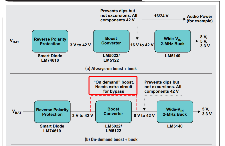
         In slyt707 document, it says when you use lm5122 boost and bypass mode, you need extra circuit for bypass as shown in below. What is the extra circuit? The datasheet only mentions that the output    voltage should be at least 9V and low leakage boot diode. What else needs to be done to use auto bypass mode?

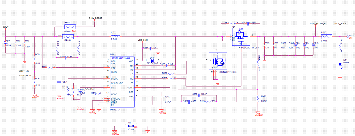
My input is 5~36V, and output is 10V, 15A. Nominal voltage is 12V. So most of the time, it will work in bypass mode. please help to review below schematic and provide suggestions. Thanks a lot!

Leo Liu.


  • Hi Huanhuan,

    Thank you for your interests in the LM5022 or LM5122. The extra circuit may be needed if you want bypass the rectifier diode with a FET, which will be the case of the LM5022, but not the LM5122. If VIN is higher than you required VOUT, then the LM5022 or LM5122 will not switch. With the LM5122 the sync FET will be turned on. However, with the LM5022, it is a non-sync boost and uses diode rectifier, and it can become lossy. A simple way is to add a PFET in paralllel with the rectifier diode and you can turn-on the PFET by pulling down the gate to GND to bypass the rectifier diode when the boost is not switching. You may also use an NFET but you need additional driver, more complex than driving the PFET.

    Hope this clarifies.

    Thanks,
    Youhao Xi, Applications Engineering
  • Hi Youhao:

    So for LM5122, I just need to design as a normal boost converter, and it will automatically pass through when vin is higher than vout. Am I correct? 

    Thanks!