This thread has been locked.

If you have a related question, please click the "Ask a related question" button in the top right corner. The newly created question will be automatically linked to this question.

TPS61099: Fixed boost converter (3.6V) generating well above its desired value (5.6V)

Part Number: TPS61099
Other Parts Discussed in Thread: TIDA-050010

Hi,

I have the exact same problem as a locked post, but it seems that the post never has a specific resolution? Could you please share the resolution with me? I am copying it here for posterity:

####################

Hello,

We are noticing a strange phenomenon with the TPS610995. Vin=3 Vout=3.6 fixed

  1. If we startup the device with the 3V bench power supply without a current limit, the output comes up to 3.6V just fine.
  2. If we startup the device with the 3V bench power supply current limited (200mA), the supply hits the limit and the device outputs less than 3.6V
  3. If we start increasing the current limit, the device output voltage will rise up to 3.6V. However the bench supply is still hitting current limit.
  4. If we increase the current limit further until it no longer hits the limit, the output voltage of the device reaches 5.6V. However the current flow drops dramatically at this point.

I'm not sure how it's possible with the internal feedback resistors for this device to ever output greater than 3.6V.

Is there something with this current limit process that is putting the chip into a weird state?

Let me know if there is any other pieces of data you need.

####################

Thanks,

Jeremy

  • To add a few other details, the boost converter is powering a cellular radio from a battery, but right now I am just testing it with a bench supply. Output capacitance is approx 220uF (the radio has two parallel electrolytics as decoupling), but the actual PCB layout for the TPS610995 is almost exactly the same as the datasheet, using the exact specified Wurth inductor, and the exact Murata MLCCs. EN is connected directly to Vin.

    The circuit works normally 95% of the time.

  • Hi Jeremy,
    if the VIN is oscillating below the input UVLO voltage, and there is no load in the system, this behavior may be triggered.
    could you help to measure the VIN, SW and VOUT waveform to check this?
  • Hi Jasper,

    There is definitely load in the system, and I don't believe the system is oscillating below the UVLO but I will double check. I will try to get some oscilloscope screenshots today.

    Do you think adding a voltage supervisor to the EN pin (at say maybe 1.8V) would work around the issue?

    Thanks,

    Jeremy

  • Hi again Jasper,

    PSU supplying Vin is set to 3.3V.

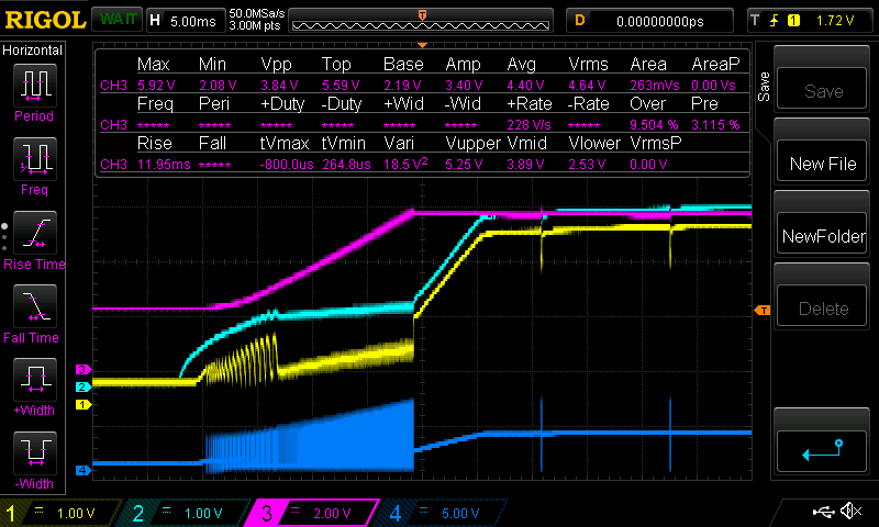
    Please see oscilloscope screenshots below. Colour coding:

    - Yellow = Vin (measured directly on the input capacitor)

    - Teal = Vin (measured at the bench power supply)

    - Magenta/purple = Vout (measured directly on the output capacitors.

    - Blue = SW (measured directly on the inductor)

    Below is the "bad" event:

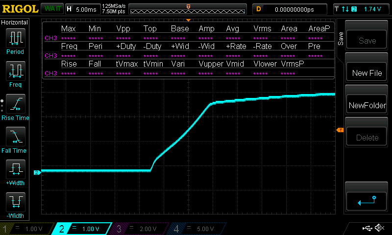
    This is the normal turn on of the bench PSU with no load applied:

    It seems there is some oscillation local to the device around the UVLO point, so it looks like I will need more input capacitance close to the converter. But my problem is also that the device can go up to 5.5V regardless of the feedback configuration; such a voltage will probably destroy the radio, and this undefined state could be triggered by attaching a depleted battery pack to Vin or a pack with otherwise poor output impedance, or by contact bounce when changing the battery.

    It seems likely to me that this could occur even using the exact reference design from TIDA-050010 (which is basically identical to what I am doing, boosting a battery to drive a cellular radio).

    Thanks,

    Jeremy

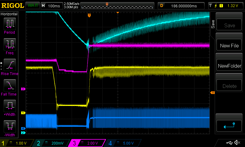
  • I have just tried adding an RC filter to the EN pin (1Meg / 1u). This gives me about 500ms delay from power on, and that seems to clear up the issue on startup. However, since the time constant of the filter is so long, if there is a glitch in the power supply (such as battery contact bounce) for around 200ms, I can get the converter to once again enter the undefined state because the EN pin is high throughout the entire glitch period.

    In this setup:

    - Yellow = Vin (measured directly on the input capacitor)

    - Teal = EN pin, after 1M/1u RC lowpass

    - Magenta/purple = Vout (measured directly on the output capacitors)

    - Blue = SW (measured directly on the inductor)

    Essentially, the problem appears to be that for a power supply with a slow rise time or glitchy startup, the device does its initial pulses on the inductor, which pulls the supply rail below the UVLO threshold, rail recovers, repeat... This oscillation eventually ends up locking up the converter in some sort of maximum duty cycle mode where it ignores the feedback loop altogether. Am I correct?

    Thanks,

    Jeremy

  • Hi Jeremy,
    thanks for the detail and the measurement. you are correct about the initial pulse causing the output voltage out of regulation. but it should not relate to max duty cycle.
    may I know the loading of the boost when the boost is powered up? the duty cycle should be very small when the VOUT is higher than setting value. so the voltage should not ramp up so high if there is some loading.
  • Hi Jasper,

    Loading is a bit hard to work out, but it is at least pushing into 220u of capacitance (2x100u electrolytic, 2x10u MLCC directly at the TPS converter as per the datasheet; this is already partially charged from before the power glitch in the second case), so there will be some current draw there. It's otherwise connected directly to the cellular modem, which on startup is supposed to have a current draw of maybe 30-40mA, but that is fairly opaque to me as it is an off the shelf radio which I don't have any control over. It may have some sort of POR delay internally.

    I have ordered some 1.8V voltage supervisors which I will try to connect to the EN pin when they arrive. Although this negates the 0.7V startup spec of the converter and the UVLO functionality, hopefully it can improve the stability. I am also going to try a zener diode on the output to clamp the overvoltage condition, but I am concerned about leakage current in this situation because this is a low power application.

    I have run the converter deliberately disconnected from the load, with only the 2x10u output capacitors. In that case, it outputs 3.8V (which is still reasonable I believe).

    Thanks,

    Jeremy

  • Hi Jeremy,
    from your description, external loading is not reliable solution. I understand your concern about leakage current if using zener. voltage supervisor seem to be the only suitable solution now.
    may I know which kind of battery is used in your system? is all the loading connected to the output of the boost. i'm thinking if there is other solution.
  • Hi Jasper, There are multiple options for the battery depending on the assembly type in this product. It will be either LiSOCl2, 2P LiFePO4 or 2P2S alkaline, so I can live with the 1.8V startup as all of these batteries will be very empty at 1.8V. But I have another project coming up in which I was hoping to use a single alkaline. The system right now has an LDO straight off the battery in parallel to the boost, but I’m planning on changing that so that all power goes through the boost. So all load will be on the boost. Thanks, Jeremy
  • Hi Jeremy,
    for the current application, is it possible to control the EN pin through the an I/O of the system. I'm thinking if we can enable the boost only after the input voltage is ready.
  • Hi Jeremy,
    I haven’t heard back from you, I’m assuming you were able to resolve your issue. If not, just post a reply below
  • Hi Jasper,

    Sorry for the delay, end of year break and all!

    I have indeed solved my issue with a voltage supervisor, the BU4820 (2.0V threshold, ~0.5V startup) and a 1M pullup on the EN pin. My application needs the boost converter to power the whole system in its latest revision, so it cannot be enabled via MCU. I wanted to use one which has a reasonably long delay, but I was having difficulty finding one with a low enough startup voltage to preempt the boost startup voltage.

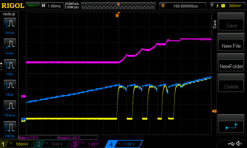
    I have tried for the past hour to reproduce the issue with these modifications and I haven't been able to. So I am going to consider this solved. See below for a scope shot:

    purple = boost output

    yellow = EN pin

    blue = boost Vin

    There are still some glitches on the EN pin, but I will add a capacitor to solve that.

    I think it is very important that TIDA-050010 is updated, as well as the TPS61099 datasheet with these caveats; I'm was the exact same configuration and battery as the TIDA note and it caused this problem. Is there some sort of IC revision or equivalent chip available from TI which does not have this startup issue?

    Thanks,

    Jeremy