This thread has been locked.

If you have a related question, please click the "Ask a related question" button in the top right corner. The newly created question will be automatically linked to this question.

LM5026: Forward Converter Light Load Problem with Output Inductor Current

Part Number: LM5026
Other Parts Discussed in Thread: LM5025, UCC24610, UCC24612

I've designed a forward converter with the LM5026. It seems there is a fundamental problem with the forward converter topology when using secondary side FETs.

At light loads, IL will be able to become negative through S4. This is a huge problem, because when S4 turns off L-output will have nowhere to freewheel. All it can do is break-down S4.

Indeed, in my prototype I see that S4 runs in avalanche during light-loads where IL is forced to go negative. The converter actually overheats for zero output load, but works fine for 5A output current.

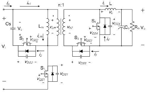
What am I missing here? How do you actually make these converters work correctly for light load? Turning off S4 at IL zero-crossing so that the inductor current never goes negative would solve it, but accomplishing that goal would be quite tricky and probably require some fairly expensive very-high-speed low-offset comparators.

  • Hello Tyler,
    You have omitted your method of driving synchronous rectifiers S4 and S3.
    I think your issue is in your implementation of synchronous rectification and not in the LM5025 active forward controller.
    Have you looked at the UCC24610 , UCC24612 ?
    Does your test board work with diode rectifiers ?

    Regards
    John
  • It's definitely not the fault of the LM5026 in this case. It's an issue of the topology.

    Those control chips could be useful.

    Currently I'm driving the gates passively as suggested in the LM5026 datasheet. This does not emulate diodes and keeps the inductor in CCM which is the problem. Those diode emulators would solve that problem.

    Yes the design works with diode rectification as the inductor current can never go negative.