This thread has been locked.

If you have a related question, please click the "Ask a related question" button in the top right corner. The newly created question will be automatically linked to this question.

LM5175: Problem of high driver

Part Number: LM5175
Other Parts Discussed in Thread: LM5176

Hi

I used LM5175 as controller of my buck-boost circuit with the input range of 12~42V and output of 20V.

The switching frequency is 300kHz.

In the boost mode, the high mosfet of left-hand is conductive all the time with the  2 mosfets of right-hand switching alternatively.

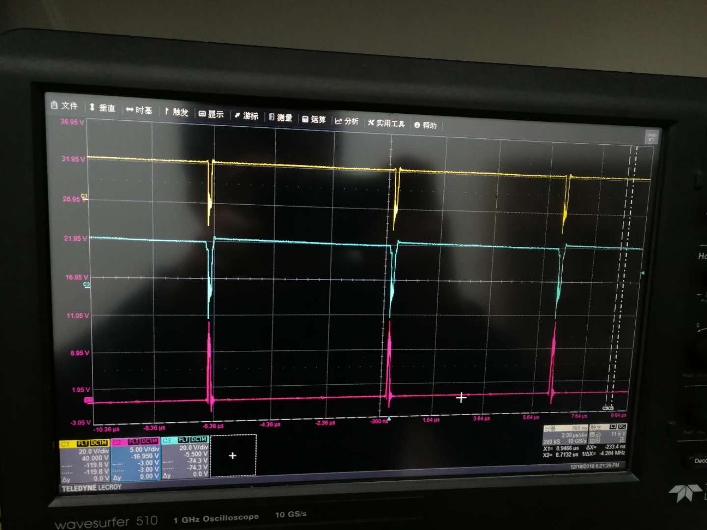
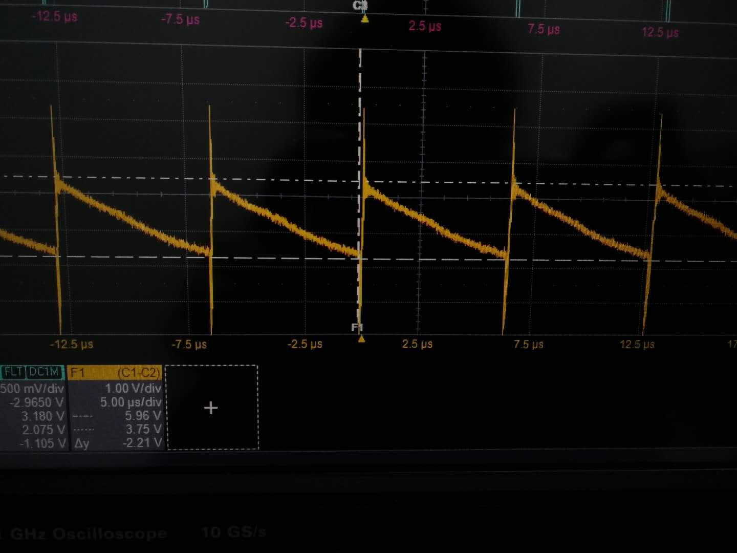
In the buck mode,the  2 mosfets of left-hand switching alternatively,but the gate voltage of high mosfet  of right-hand has a  drop every 2 periods. 

Thus it was a problem with the waveform of switching node ,driver output and so on......

Somebody can help me ?

The waveform in buck mode : right-hand switching node(Yellow), right-hand high mos gate(Blue) and right-hand low mos gate(Red)

  • Hi Feng,

    Thank you very much for using the Lm5175. It seems you circuit is in the buck-boost mode, not the buck mode. In the buck boost mode the left and right switch leg operate alternatively every other cycle. As long as the output regulation is kept, this should be fine.

    You may also consider to replace the LM5175 with the LM5176. They are pin-to-pin compatible but you just need to replace RT resistor to stay at the same switching frequency. The LM5176 is a new part with better noise immunity implemented for a more robust performance, and you should have a better experience.

    Thanks,
    Youhao Xi, Applications Engineering
  • Thanks for your reply and recommendation.

    I tested the circuit with input of 28 V and  output of 20 V so it's unlikely that it worked in buck-boost mode,which can also be explained by the waveform i posted as follow:

    28 V input and 20 V output : SW 1 (Yellow), SW 2 (Red)

    The waveform of SW1 and SW2 should have the same period if the circuit works in buck-boost mode,doesn't it ? 

    The SW1 has the same frequency with the intended switching operation but the SW2 has a twice times period.

    And the Drive waveforms of 4 mosfets :

    28 V input and 20 V output :HDRV1(Yellow), LDRV1(Red), HDRV2(Blue), LDRV2(Green)

    As we can see,the right-hand high mosfet that should have been conductive all the time was shut off every 2 periods.

    What's wrong ?

    Thanks again for your patience.

  • This may be BOOT precharging signal: in buck mode the right hand high side FET is supposed to be always on but it requires the BOOT voltage to be above the BOOT UV. See your HDRV2 signal it is dropping and may trigger the BOOT UV so the LDRV2 is triggered to charge up BOOT2. The BOOT2 . Do you placed a resistor across the MOSFET gate and source? Or you used a very small BOOT capacitor? The capacitor should be 0.1uF. Replace the capacitor with a new one in case a wrong capacitor was installed by accident. If you have a resistor across Gate and Source, remove it or change it to a large one like >20k.
  • Thanks.

    There is  no resistor placed across the gate and source and the boot capacitor i used is 0.1uF. And i replaced it with a new one but it doesn't work.

    You reminding me of the Cboot. Maybe i found the reason why the HDRV2 trigger every 2 periods.

    The Cboot of HDRV2 is discharging all the time and it's voltage is down close to the Vuv(boot).

    So what makes it  to discharge itself?Maybe there is a discharging path i have never find?