This thread has been locked.

If you have a related question, please click the "Ask a related question" button in the top right corner. The newly created question will be automatically linked to this question.

WEBENCH® Tools/UCC28600: Designing poblems

Part Number: UCC28600
Other Parts Discussed in Thread: TL431

Tool/software: WEBENCH® Design Tools

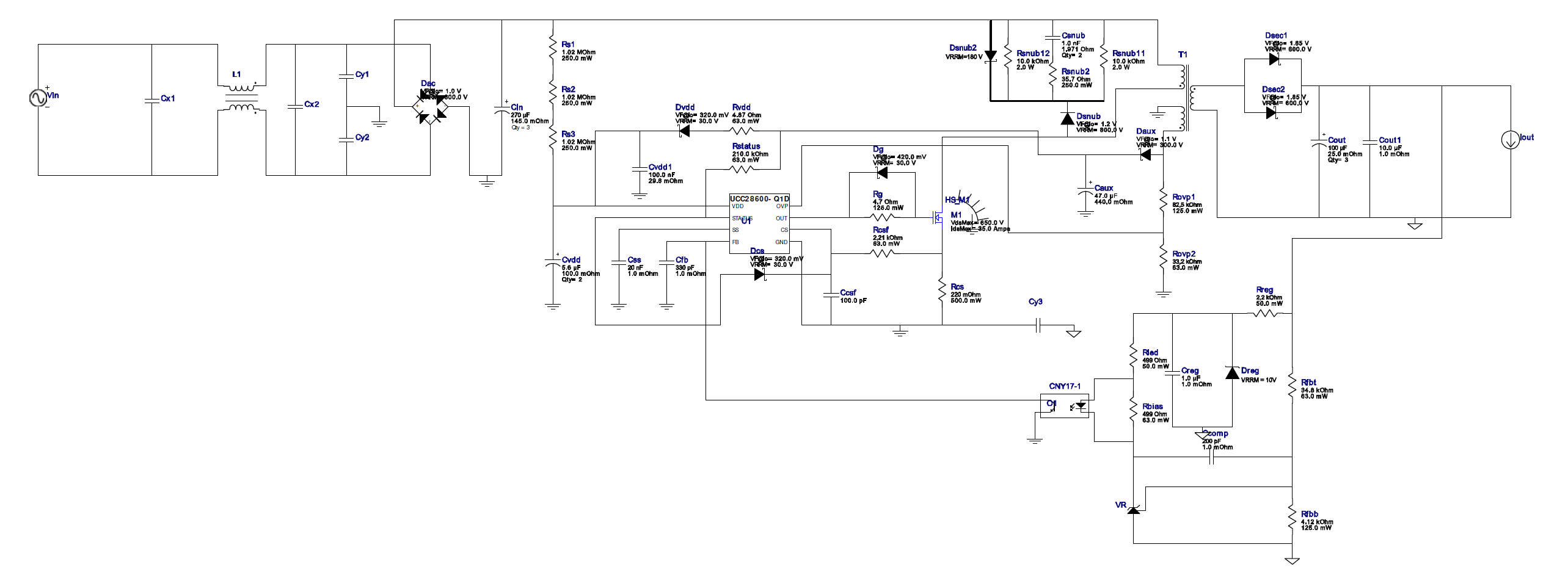
Hey, I want to design a flyback with the ucc28600 with an input voltage from 40VAC to 265VAC and a ouput voltage of 24V (40W). I use and instead of a start up resistor a linear voltage regulator.

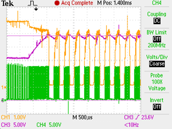
The circuit in the webench software doesn’t work and the feedback circuit of webench makes no sense. So I tried the excel document with the feedback circuit from the 65W evaluation module. But it doesn’t work too. It only works from about 40VAC to 65VAC over the hole output power range. I measured the feedback pin and it discharge the feedback capacity every cycle completely. Could this be the problem?

At an input voltage of 65V and a output of about 20W the output voltage is flatting between 24v and 15V.

With increasing input voltage the IC only works with decreasing the output power and stops working immediately after the output reaches the output voltage of 24V for the first time.

Isn’t it possible to design a flyback with this IC over the hole input voltage range or what could be the problem?

  • Hello MM86,

    Thank you for your interest in the UCC28600 flyback controller.

    Certainly it is possible to design a 40-W, 24-V flyback converter operating from 40Vac to 265Vac using this controller.
    The 40Vac low-end input is an unusual requirement, but it is not impossible to accommodate. A relatively large value of bulk capacitance will be needed to keep the minimum ripple valley voltage high enough to keep the transformer turns ratio reasonable.

    It is not possible to determine the cause of your limited output power and voltage from the description you provided.
    Do you have a physical prototype board operating (or partially operating)? If so, can you provide the schematic diagram of it, please?
    Also provide the details of the transformer being used (inductance, turns ratios) and a copy of the Design Calculator Tool you used to generate the component values.

    I do not understand what you mean by "I measured the feedback pin and it discharge the feedback capacity every cycle completely."
    How are you measuring the feedback pin? Oscilloscope probe? Voltmeter? Something else?
    What "cycle" are you referring to: the switching cycle or the ac-line cycle, or some other cycle? ( I can't imagine that the capacitance on the feedback node can discharge and recharge every switching cycle. ) If you can provide some waveforms, this can also help to resolve your issues.

    Regards,
    Ulrich
  • Thank you for your fast feedback. Attached you can find the excel document I used to calculate the values.

    The transformator has the following values:

    NPri/Sec=5

    NPri/Bias =10

    LP = 109uH

    The circuit is nearly identical with the following circuit. Only the startup circuit RS1, RS2, RS3 was changed by the linear voltage regulator, which delivers a constant voltage of 14V.

    The problem I mentioned above was, that the voltage at Cfb is getting down to zero every cycle. The following oszi screenshot shows this problem. It was taken by 66V and about 40W output power, but this problem I have by lower input voltages too.

    CH1=Cfb

    CH3=Output Voltage

    CH4=Gate Voltage MOSFET

    The trafo was coiled myself and it is sometimes noisy. Could the trafo be the cause for the problem? Is the circuit in principle correct? Can you say me, what I have to change, so that it works?


    slvc104j - TI - Kopie.xls

  • Hello MM86,

    Thanks for providing the additional information.

    Looking at the FB signal behavior, this looks like a large-signal instability. I assume that VR in the schematic is a TL431 shunt regulator.
    (If it is something different, please let me know.) The compensation cap Ccomp is only 200pF. Normally, I'd expect this value to be much larger (at least an order of magnitude or more), sometimes with a series resistance. This may be the main cause of the instability, but there may be other contributors.
    I'll step through the design calculator and verify that the values make sense and that the schematic matches it.

    The audible noise from the transformer is probably from the on-off nature of the unstable operation seen in the screenshot.
    Also, hand-made transformers are usually "loose" and can vibrate more easily than varnished ones. Don't worry about your trafo yet.

    The circuit arrangement looks correct, in principle, but various component values may not be correct.
    I'll need some time to analyze this information. I hope to have a response in a day or two.

    Regards,
    Ulrich
  • Hello MM86,

    A review of your Calculator spreadsheet shows no significant problems. The schematic diagram that you provided appears to have been generated by the Webench design tool. I think that some of the components recommended by Webench are not the optimal choices for the application, but they are not the cause of the unstable operation that you are experiencing.

    I believe it is due to improper loop compensation values, particularly Rled and Ccomp.
    Please refer to this design guide to redesign your compensation network properly: www.ti.com/.../slua671.pdf

    I hope this resolves your issue.
    Regard,
    Ulrich