This thread has been locked.

If you have a related question, please click the "Ask a related question" button in the top right corner. The newly created question will be automatically linked to this question.

TPS1663: Parameter tCL_PLIM(dly)

Part Number: TPS1663

Hi.

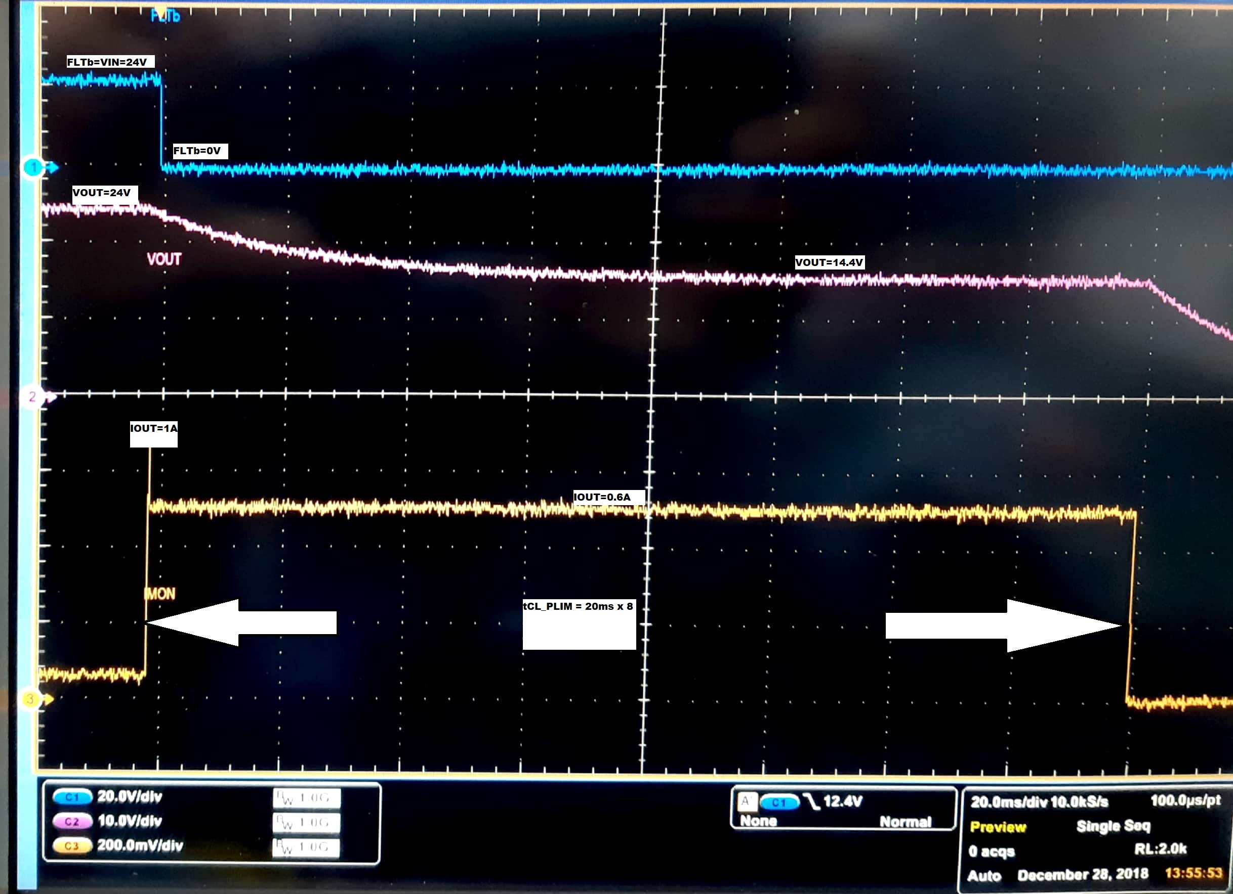
Is the TPS16630 using the tCL_PLIM(dly) =162ms for the current limit before the output turns off (trips)? Or it is only the TPS16632 that does that? x32 trips for both current and power, but x30 only for current? Or do they only trip for thermal?

  • For TPS16630 tCL_PLIM(dly) parameter applies for current limiting only, TPS16630 does not have power limiting,
    For TPS16632 tCL_PLIM(dly) parameter applies for current limiting and power limiting both.

    For both devices, in case of overload or overcurrent if Thermal shutdown temperature is reached before a time of tCL_PLIM(dly), the device will turn-off the internal FET and the subsequent operation (auto-retry or latch OFF) will depend on the MODE pin configuration.
  • For TPS16630; tCL_PLIM(dly) parameter applies for current limiting only, TPS16630 does not have power limiting,
    For TPS16632; tCL_PLIM(dly) parameter applies for current limiting and power limiting both.

    For both devices, in case of overload or overcurrent if Thermal shutdown temperature is reached before a time of CL_PLIM(dly), the device will turn-off the internal FET and the subsequent operation (auto-retry or latch OFF) will depend on the MODE pin configuration.
  • Can you please explain the 162ms timer CL_PLIM(dly)?
    Does the eFuse ever trip by this timer (trip time), or what does it do? Or does the TPS16630/32 only trip by thermal?
  • Hello Magnus,

    tCL_PLIM(dly) is the maximum time for which the device can remain in current limiting or power limiting. If thermal shutdown temperature(TSD) is reached before this time (tCL_PLIM(dly)) while the device was in Current/Power limiting, the device will shutdown before tCL_PLIM(dly).
  • If I load the TPS16630/32 EVAL board with 1A with limit set to 0,6A, the TPS16630 heats up unitl it turns off many seconds later (by heat). It never turns off after 162ms.
  • Hello Magnus,

    Is the load of 1A applied at start-up (VOUT, VIN is Zero) or after the device has started up (VOUT has reached VIN).

    if load is applied on start-up, this is expected. Please refer to section 10.2.1 on page 22 of the datasheet (http://www.ti.com/lit/ds/symlink/tps1663.pdf )

  • Hello.

    My 1A is applied after the Vout has stablilzed to Vin. The 162ms timer does not turn of the FET. Why? My threshold is set to 0.6A.

    By "expected", you rather mean that you are aware of the problem and will fix it in the released version of this device? That's what I understand from 10.2.1.

  • Hello Magnus,

    As per test done on EVM with 0.6A current limit, 24V Vin and 24ohm load on output, tCL_PLIM is ~160ms. Please see below scope capture.

    For this test, a load of 24 ohms was connected on OUT after VOUT has reached VIN (24V) with current limit of 0.6A through Jumper J4 on EVM.

    Can you share the test conditions (VIN, Load resistance) and waveform for VOUT, FLTb and IMON captured on a oscilloscope?

    For section 10.2.1, the thermal regulation timeout (on start-up) will be fixed in released version of the device.

  • Hello.

    Please se 'scope picture below. Signals and "DIV's" are in the same order and scale as you have them.

    The FLTb1 never drops and the IC is going hot. FYI I have removed the large output cap.

  • Hello Magnus,

    We could not see the behavior that you provided in scope shot above after removing the 1mF on OUT.

    Was the Jumper J5 open or Closed for the above test? (Auto-retry or latch)

    Can you let us know the below voltages and current measurements (With multimeter)  while the device is in above state of current limiting and FLTb is high.

    • Voltage on IN, OUT, ILIM and dvdT pins
    • Current drawn from Input source

    Also let us know if you find this behavior with other current limit settings (6A, 4.5A, 2A, 1A on Jumper J4).

  • Hello.

    J5 was closed during the test.

    Voltages when current-limiting for setting 0,6A:

    Vin=24.18V

    Rload = 28R

    Vout = 18,40V and dropping slowly

    V(Ilim) = 0,493V

    V(dvdt) = 4,21V

    Other current setting does not seem to make any difference in behaviour.

    Another thing I noticed: In manual mode, it is enough to just touch TP2 with a fingertip to restart. No need to touch the button S1.

  • Hello Magnus,

    Please refer to below for auto-retry behavior with over-current of 0.85A for ILIM set to 0.6A. The device auto-retires and fault is set to high after the over-current condition is removed. There was no effect on touching TP2 (SHDNb).

    Was the ILIM voltage decreasing with decrease in input current in your above observation?

    Device in auto-retry CH1 = FLTb, CH2=IMON

    FLTb goes high after the over-current condition is removed [CH1 = FLTb, CH2=IMON]

  • Hello.

    When measuring with multimeter, ILIM was slightly decreasing as the IC was heating up.
    I do not get this behaviour. See my picture below, where TOP=Vin, MID=Iout, BOT=FLTb.

    The sensitive SHDN was in manual mode, not auto-retry. I touched this test point while resting my other hand on the electronic load chassis. This combination made the IC to reset. The LED was indicating RED, but when I touched the test point, it changed back to GREEN. Does the pin require a pull-up?

  • Hello Magnus,

    There seems to be some interference or inconsistency from the electronic load. it looks like load is pulsed as you can see in blue waveform above.

    Can you try testing with a passive resistor (20-30 ohms).
  • Hi.

    I have tried with 28R power resistors. The pulses we saw is now gone, but it still only triggers for overtemperature. See picture with IMON (cyan) and FLT (yellow). Eventually (several seconds later when temperature is high, the LED's changes from green to red).

    I also tried the other channel with the TPS16632 (same marking as TPS16630) with same behaviour.

  • Hi.

    I have until now been supplying from a PoE (802.3at) splitter with 24VDC output. When I change to a lab PSU it works, and I get the 162ms.

    But the 24V output from the PoE splitter is nice and stable, even in the 28R connection transient.

    I did some experimenting and found that the IC needs more input capacitance to work with the PoE splitter. The 1uF on the EVAL board is not enough if suppplied from something else than a laboratory PSU. 10uF seems to work well. I think you should update the datasheet with this.

    But there is still the spooky SHDN behaviour in manual mode, just touch the test point and the e-fuse is enabled again.
  • hello Magnus,

    Did you observe spooky SHDN behavior with Laboratory PSU? or only with PoE 24V adapter.
  • With LAB PSU it is not spooky.

    If I add 100nF across S1, then it works great with the PoE adapter.

    Please consider my recommendation with 10uF for Vin and 100nF on SHDN when updating the datasheet. And forward information to your IC designer.

  • Thanks Magnus, we will consider your recommendations. Let us know if you have any further query.  I am closing this thread.