


Dear all:
At present, there is a problem in debugging. The discharge MOS DS is connected with an electrolytic absorption shut off DS peak in parallel. After turning off and discharging MOS, the current slowly drops and the capacitor is charged.
After charging to a high point, the capacitor discharges. At this point, the capacitor returns to charge the battery, causing the current to become negative. When discharging MOS GS, it begins to oscillate.
GS oscillation stops. The oscillation amplitude of GS increases with the increase of current, and when the current is large enough to a certain value, MOS is turned off, and GS oscillation will cause MOS re-conduction or amplification of the blasting machine.
The original intention was to turn off the DSG and turn off the CHG at the same time as the >50ms to avoid current reversal, but when the hardware triggered protection turned off the DSG, I also had to read sys_stat
If the protection is triggered, then manually close CHG, but the speed cannot keep up with the speed of the hardware, when I close CHG
When the oscillation has already occurred.(the oscillation starts around 80us after turning off DSG)
In addition, as long as I put the operation of reading the SYS_STAT register into the interrupt to read, the communication between MCU and BQ76920 will often have errors,BQ_ReadBlock will often have CRC check errors, or Bq769x0IIC_Wait_Ack will not receive a reply, and the CC_EN in SYS_Ctrl2 will always be set to 0 automatically after running for a period of time.
If the interrupt is only the setting flag bit, it is normal to read the register outside the interrupt. However, it cannot keep up with the speed of hardware closing DSG.
Is there any other way for IC to turn off DSG and CHG simultaneously when triggering protection?
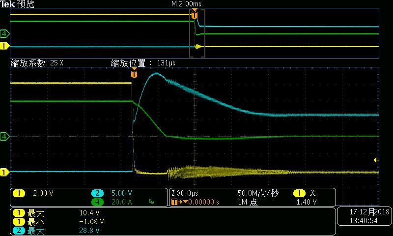
Yellow is discharge MOS GS signal
Green is current
Blue is discharge MOS DS signal
The figure above shows that when the discharge current is 300A, MOS will be switched off and discharged (it will not oscillate when it is less than 300A).
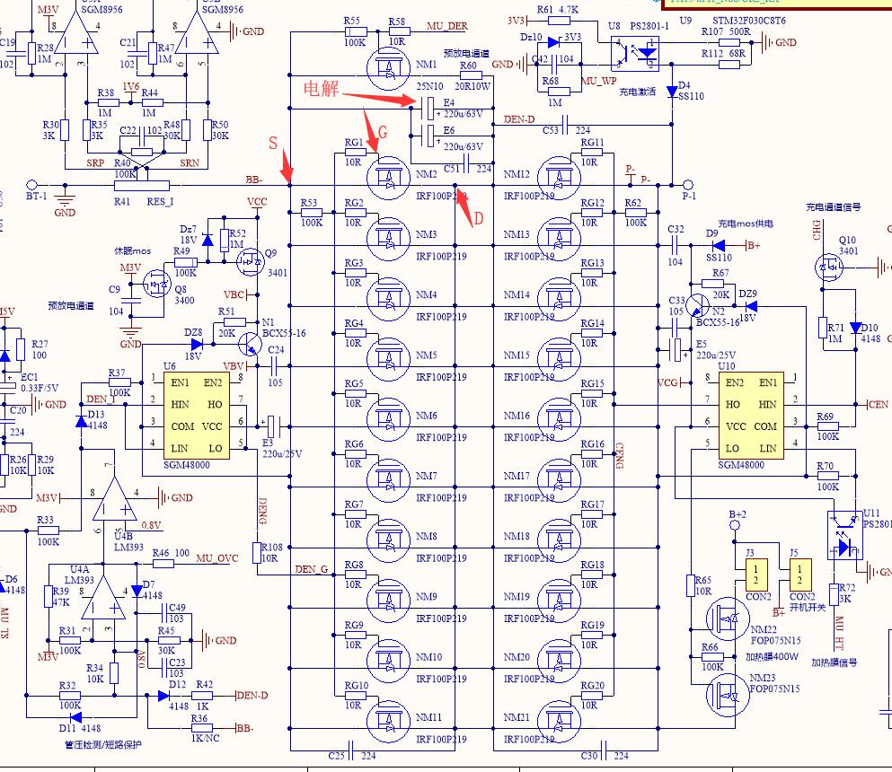
The above is the corresponding schematic diagram. A diode is connected in reverse parallel between the discharge MOS D pole and the positive electrode of the battery.
