This thread has been locked.

If you have a related question, please click the "Ask a related question" button in the top right corner. The newly created question will be automatically linked to this question.

TPS3850: Enabling watchdog in case SET0 = 0 and SET1 = 1

Part Number: TPS3850

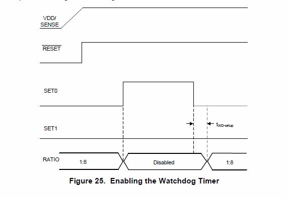
This diagram in section (7.3.5.1.1 Enabling the Window Watchdog) shows the states of the watchdog in case the enabling configuration is SET0 = 0 and SET1 = 0.
I am trying to deduce what would be the diagram in case the enabling configuration is SET0 = 0 and SET1 = 1.

As per my understanding the sequence of steps will be: (Assume RESET pin is always HIGH)
SET0 = 1 , SET1 = 0, Watchdog state: disabled
SET0 = 1, SET1 = 1, Watchdog state: ?????
wait Tset,                   Watchdog state: ?????
SET0 = 0, SET1 = 1, Watchdog state: enabled with ratio 3/4 after Twd-setup
SET0 = 0, SET1 = 1, Watchdog state: ?????
wait Tset,                   Watchdog state: ?????
SET0 = 1, SET1 = 0, Watchdog state: disabled


My question is what would be the watchdog state in the intermediate steps above?

Thanks.

  • Mohamed,

    Please refer to the Time Requirement Table 6.6 on page 6 of the datasheet. This provides all of the different SET pin configurations. Let me know if you need additional support. Thanks!

    -Michael
  • Hi Michael,

    Thanks for you reply, I know about timing requirements in 6.6 but this is not what I am asking for, my understanding is that the timing requirements in 6.6 will not apply if reset event didn't occur, which is the case here, so could you please check the question again or maybe tell me if I am misunderstanding anything?

    Thanks.
    Mohamed Mounir
  • Mohamed,

    These times are the windows in which a pulse must arrive to cause a reset. These are not the reset delay times once the reset occurs. The SET pins and CWD pin configure the watchdog timeout and the CRST pin configures the reset delay time.

    When you transition from one SET configuration to another, the timeout remains in the previous SET configuration until the reset occurs, then the new SET configuration will determine the watchdog timeout. There is also an initialization delay when enabling the watchdog. Please let me know if this answers your question. Thanks!

    -Michael
  • Hi Michael,

    "These times are the windows in which a pulse must arrive to cause a reset" I think you are referring to Twdl and Twdu, so do you mean "windows in which a pulse must arrive to (prevent) a reset"? if not what are these timings that must arrive to cause a reset?

    Regarding my question I am not sure if I can deduce the watchdog intermediate states from your answer, do you mean that watchdog states will be:

    SET0 = 1 , SET1 = 0,Watchdog state: disabled
    SET0 = 1, SET1 = 1, Watchdog state: disabled
    wait Tset, Watchdog state: disabled
    SET0 = 0, SET1 = 1, Watchdog state: enabled with ratio 3/4 after Twd-setup
    SET0 = 0, SET1 = 0, Watchdog state: disabled
    wait Tset, Watchdog state: disabled
    SET0 = 1, SET1 = 0, Watchdog state: disabled
    Assuming after first reset watchdog was configured to be enabled with ratio 3/4 and no other reset events occurred.

    Are the watchdog states in the sequence above correct? if not can you write the same sequence above with the correct watchdog states? this will directly answer my question and resolve my issue.

    Thanks.
  • Mohamed,

    The only "disable" state is with SET0 = 1 and SET1 = 0 as indicated in the Timing Requirements Table. For the other SET pin configurations, you will need to also check the configuration of the CWD pin as the SET0, SET1, and CWD pins set the watchdog timeout. During the watchdog timeout, if a pulse does not arrive, the watchdog will trigger the watchdog output to fault logic low status.

    Example,

    If you have SET0 = 0, SET1 = 0, and CWD as no connect/floating, your watchdog lower boundary will be 22.5 ms and your upper boundary will be 55 ms. This means a pulse must arrive between 22.5 ms and 55 ms otherwise WDO will trigger. If pulse arrives before 22.5ms or after 55 ms, WDO will also trigger.

    The watchdog ratio is only for the situation where you program the watchdog timeout with a capacitor on CWD. Please review Adjustable Capacitor Timing section in the datasheet for more information about programming the watchdog timeout.

    -Michael
  • Do you mean that the highlighted phrase only applies on changing reset delay timings, but for changing watchdog timing window RESET event is not needed and changes will take place immediately?

    Regards,
    Mohamed Mounir

  • Mohamed,

    Anytime you change the SET pins during operation, you need to trigger a reset in order for the new changes to take effect. The SET pins set the timeout. Only the CRST pin sets the reset delay. The watchdog timeout is set by SET pins and CWD.

    Please let me know if you have additional questions. Thanks!

    -Michael