A related question is a question created from another question. When the related question is created, it will be automatically linked to the original question.
If you have a related question, please click the "Ask a related question" button in the top right corner. The newly created question will be automatically linked to this question.
I'll try to help you. Thank you for considering the UCC28881 for your auxiliary supply. Certainly, a 45-V overshoot is unacceptable.
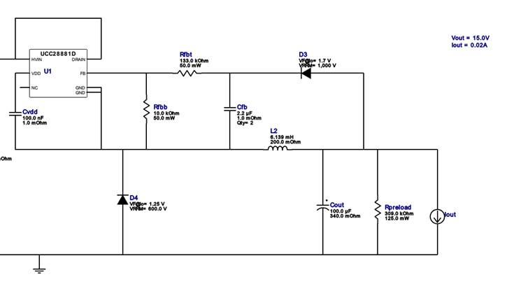
I see that the schematic provided appears to be a portion of a Webench design. The UCC28881 is placed as the high-side switch of a buck topology.
A huge overshoot may result from a few possibilities:
1. Slow loop response: Perhaps Cfb does not charge up quickly enough to prevent the overshoot at start-up.
2. Inductor saturation: A small 6mH inductor may saturate while charging Cout and a high peak current may overcharge Cout before the current limit can shut down the IC.
3. Insufficient loading: The indicated preload resistance is ~300K which may be too "light" to throttle back an overshoot in conjunction with slow loop response (#1). A significant overshoot implies no load at start-up.
If you or your customer has a current probe available, please check the inductor current at start-up to confirm or refute #2.
Also, please verify that the components on the board match the values and specs of the Webench design recommendations.
Sometimes a wrong part can be loaded even though the schematic appears to be okay.
Can you provide more details about the aux supply requirements? For Vin = 270V, is this DC or AC? Is there a min-to-max range?
As a test case, I filled out the UCC28881 Design Calculator Tool (www.ti.com/.../getliterature.tsp ) using 250V min, 270V max, DC input, 15V, 20mA, 70% eff.
The results recommended 0.37mH (instead of 6mH), ~160uF (instead of 100uF), 26K preload (instead of 309K), and 0.813uF feedback cap Cfb (instead of 2.2uF).
I recommend that you use this tool to calculate the proper values for your application and modify the prototype to conform to those recommendations. Make sure that the inductor is designed to not saturate (with margin at high temperature) at the peak current during start-up and transients. This peak may be higher than the peak indicated in cell E28. Verify with the current probe.
Today we received a separate E2E posting (e2e.ti.com/.../759416) from Leonid Brusser who uses identical wording to describe his problem. Can I assume that this is the customer to which you refer in your original posting?
If so, then it can be more efficient for TI to support the customer directly rather than second-hand through an intermediary.
Please verify if this is the case, or if there are extenuating reasons to continue support through this thread.
I'll close out this thread and continue to support Leonid on his thread.
Although it is not actually resolved yet, I need to mark this thread as "resolved" to close it out.
You can track progress on the issue by monitoring that thread, which is unresolved.