This thread has been locked.

If you have a related question, please click the "Ask a related question" button in the top right corner. The newly created question will be automatically linked to this question.

UCC28070: ERROR(ORPSIM-15090) and WARNING(ORPSIM-15256)

Part Number: UCC28070
Other Parts Discussed in Thread: UCC27524

Hello, dear friends. Please don't ofended by badly language, I'm from russia, thanks.

I have troble with simulation your pspise model UCC28070.

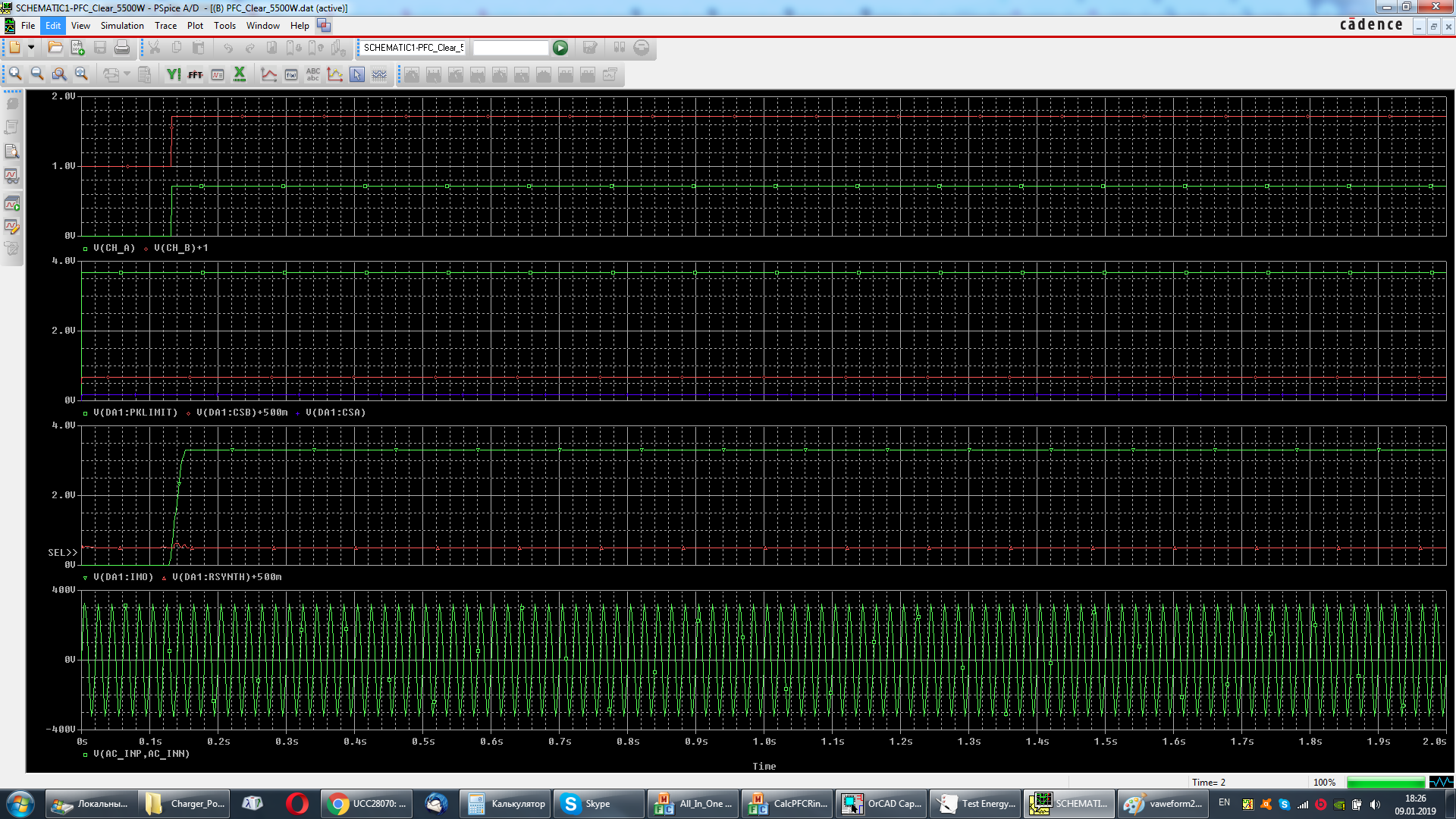
I intagrated transient model (slum097) im my progect ( not used BOOST_AVG model).

I am connect PINs "IRIPA", "IRIPB" and "F_KHZ" across resistors 100meg into GND (to not break the simulation)
I get error message:

WARNING(ORPSIM-15256): <X_U7.X_U9_U11_U55.T> not a subcircuit param

ERROR(ORPSIM-15090): FOUR device VIN is undefined

How do i fix this errors, psise model crypted and i dosn't edit this parametr in the model editor or other editor (example notepad++)

I'm use Orcad 16.6 full licenses.

I'm calculated Project 5.5 kW in mathcad and WEBENCH.

My project in attachment.

Thanks!PFC_5500W-PSpiceFiles.zip

  • Hi Denis,

    I have contacted another resource within TI to check this issue.
    But please understand that the responses may be delayed due to holidays.
    I will also follow up on this post. Thanks.

    Regards,
    Teng
  • Thanks. When do you have holidays? in rusia official holidays and non-working days 30 december-08 january, but I work in this days in home, outside office and I will track information on this post as well. If I find a solution, I will definitely describe the principle of its solution.
  • Hi Denis,

    The winter holiday usually runs from Christmas through new year although many people choose to return around the second week.

    If you created your PSPICE project by modifying slum097 and still uses the simulation profile "Startup-tran", please note that it enables Fourier analysis of the current through VIN. If your schematic no longer contains a voltage source VIN, the simulation won't work.

    To fix this, please edit the profile, click the button "Output File Options" and uncheck the box next to "Perform Fourier Analysis", then try the simulation again.

    Thanks,
    JC
  • Thanks. Errors disappeared after offclude analise Fourier. But my simulation schematic doesn't work. Voltage on Chanel A and Chanel B equals some microvoltes. I'm tested with and without boost_block (parallel on my power parts). If used reference designe voltage on Chanel A and Chanel B have a sinusoidal vaweform whis amplitude 400mV. Because, i'm understand model UCC28070 Trans it's doesn't work on different designe power part, except boost_block?
  • I'm create new project it's clear (but non use slum097 profiles reference designe). In a channel A and Channel B is a 700mV DC. I'm used Low-side driver UCC27524, unused pins (IRIPA/IRIPB/F_Khz) edit properties FLOAT to RtoGND.
    Waveforms simulations in my project and full archive my projectis attached on this message.

    HV_PFC_5500W-2019-01-09T15-27.zip

  • Good day! I'm used in my project Ultra fast IGBT, reference designe on slum097 willn't be abble simulate this event.
    I wish to test the work of my design before the release of the pre-production printed circuit boards. Help me please.
  • Hello Denis

    I'll try to run you sim file as soon as possible but it may be Wednesday before I am able to get to it.
    In the meanwhile I can only suggest that you try a 'divide and conquer' approach because that is likely to be the approach I will take. For example, the first thing I usually do is to replace the switches (IGBT in your case) with a voltage controlled switch. Use the GDA and GDB outputs to control the switches directly. This eliminates the IGBT and gate driver models from the problem.

    Regards
    Colin
  • Thank you very much. But global problem this spice-model (not my project), i'm think, it's doesn't normal work out-pin of GDA and GDB ( more time this pin generate direct voltage ~700 mV, instead of rectangular pulses). This informations vision on waveforms in before posts.

  • GDA and GDB it's V_CHA and V_CHB on first screen before posts. The conditions for starting the chip are met.
  • Hello Denis

    I opened your schematic today - I still have to correct some import problems - the file is not finding the model for the UCC28070 and some other parts for example.

    However, can you please check the connections for the bridge rectifiers U1 and U2 in your schematic. I simulated this sub-circuit on its own (in PSIM) and HV remains at 0V !. Please check the voltage at the +HV node and let me know if it is OK or not - obviously it should be a rectified version of the input.

    I'll wait for your confirmation before proceeding.

    Regards
    Colin
  • Model UCC28070 attache in progect and you need re-changed this model in pspice setting on library pages.

    Waveforme input signal +HV_IN attache in this message. But waveform input signal doesn't sinusoidal (positive half-wave).

    In Orcad 17.2 haven't model FGH60N60, attached new progect whis STGW80V60DF.


    hv_pfc_5500w-2019-01-17T06-39.zip

  • Hello Denis

    The +HV_IN waveform looks ok - the reason it does not fall back to zero is that there is too little load on the capacitors on this net so they don't 'follow' the sinusoidal input waveform all the way to zero. This effect will dissapear once the PFC stage is up and running (or if you add a resistor load to the net).
    It will probably be tomorrow before I get an opportunity to open your simulation files.

    Regards
    Colin
  • Hi Denis,

    We have looked into the project you shared and made the following changes.

    1. Connected IRIPA, IRIPB, FKHZ properly. Please look into the below thread to understand the functionality of these pins.

    https://e2e.ti.com/support/tools/sim-hw-system-design/f/234/p/153952/560486#560486 

    2. Used BOOST_AVG block at the output stage.

    3. Configured input rectifier circuit properly.

    PFA the updated project UCC28070_PSPICE_TRANS.zip

    Below is the simulation result

    Thanks & Regards,

    Arpan Gupta

  • Good days. I dosen't have some problems whit the project used BOOST_AVG block. My problemes connects with using own FET (IGBT) and Inductor ( 60KMu cores), this project doesn't work in this model UCC28070. I need modeling transient processe in FET and feedback, and modeling magnetic parametrs in my cores, but doesn't want to search and stydy this process on finished devises.
    e2e.ti.com/.../560486
    I read this post, but doesn't search solution my problems.
    I understand is impossible used this model UCC28070 whis own magnetic core (inductors) and fet, only used boost_avg blocks?
  • Load in my project it's 5500W, Rload=27.67 Ohm, input rectufier should be hold RMS current 50+A.
  • Hi Denis,

    The pins GDA, GDB generates average voltage of switching waveform. Hence, BOOST_AVG block is used instead of FET, inductor and capacitors. 

    Therefore, we request you to use BOOST_AVG module and change component values within this topology to match your circuit. 

    Thanks & Regards,

    Arpan Gupta

  • Good day! I need simulate magnetics parametrs and transient parametrs my fet(or IGBT) and my core (inductor) materials.

    Boost_avg block doesn't allow to consider this parametrs.

    I believe that the device will work, if choose some parametrs boost_avg dlock in my circuit, but this study will not be complete.
    I have two quetions:

    1) My project don't be resolved if is not used boost_avg? (more rhetorical question)
    2) How can I get an unencrypted model and is it possible?

    Thanks. 

  • Hi Denis,

    Below are the answers to your questions 

    1. Yes, we have to use BOOST_AVG block to get correct result.

    2. For the device, unfortunately an unencrypted SPICE model is not available for distribution. I apologize for any inconvenience.

    Thanks & Regards,

    Arpan Gupta

  • Thank you, but your answers didn't resolve my problems.
  • Hello Denis

    Arpan is the expert for the device model and knows how it behaves much better than I do. However, it seems that the problem is that the Average model isn't going to give you the level of detail of the switching waveforms that you are looking for. Have you considered using the transient model for this device which is available on the UCC28070 page ?. Of course you can expect that the transient model will run more slowly than the average model but that's the tradeoff that has to be made.

    The transient model will give you OUTA and OUTB signals which you can use to drive the IGBTs and the power stage. (the simulation may run faster if you turn one of the phases off The exact behaviour of the switching stage, IGBT plus rectifiers and the losses in the magnetics depend on the accuracy of the models for these devices and I'd suggest you discuss this with the respective manufacturers. You should also include an estimate of the parasitic inductances and capacitances due to the layout of course.

    If I had to do this myself, I would start with the best models for the inductor that I could find and use simple voltage controlled switches for your IGBT and diode. Then run the system at 50% duty cycle from a simple square wave source (no controller !) and Vin = 50% of Vout. That at least would allow you to judge if the magnetics model was behaving reasonably accurately. Once you were happy with that you could look at 2 or 3 other input/output/Duty cycle conditions and then start to introduce some more complexity. First, an IGBT, then a Diode and then the UCC28070 controller.

    This approach allows you to gain confidence in the system model you are building rather than getting bogged down in non-essential details.

    Finally, despite what I said earlier about a square wave source, I do think that your choice of the UCC28070 controller is the best one for your application.

    Please let us know how you get on.

    Regards
    Colin
  • Hello Denis

    I'm going to close this thread. I think this issue is being discussed at e2e.ti.com/.../2850474

    Regards
    Colin
  • Hello Denis

    Do you have an update to this thread or have you managed to solve the issue ?

    I'll close this thread in a few days time.

    Regards
    Colin